Wiring 3-3
IQ 2000/5000 Installation Manual
Positioning Drive Modules (DC Bus Power)
The DC bus from the PSM supplies power to the IQ-5000 PDMs. The DC bus must be connected
as shown in Figure 3.25 on page 3-25, with the PSM in the center, using the connection wires
provided.
Auxiliary Logic Supply
An auxiliary power supply module (PSM-AUX) is available to supply DC power to the logic
supplies of up to four PDMs if the PSM is OFF. The PSM-AUX uses single phase 115 VAC power
as the input.
The PSM-AUX option is useful if PDM logic power must stay on even when the motor supply
(the PSM) is off. Absolute positioning is one example of when the PSM-AUX would be useful,
since position information is maintained as long as logic power is on. Another example would
be maintaining PDM logic power so the PDM serial interface could be used for troubleshooting
and diagnostics. Refer to Figure 2.24 on page 2-31 for wiring information on the PSM-AUX and
optional PSM-AUX isolation transformer.
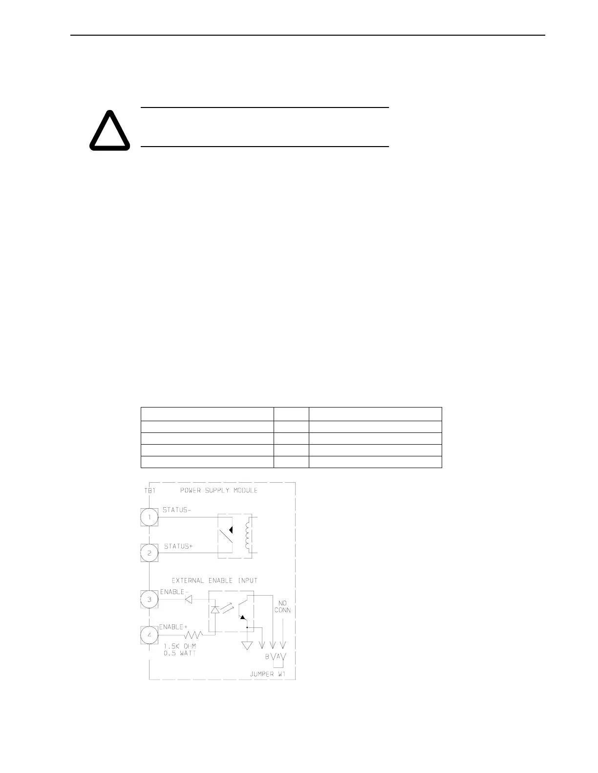
PSM Interface Logic
The Status signal and the Enable signal on the PSM are provided to interface the PSM with the
PDM or another control. Figure 3.1 illustrates typical internal circuitry for the interface connec-
tions; Figure 3.2 shows external connections of the PDMs.
TABLE 3.1 PSM Interface Signals
!
CAUTION: Do
not
substitute the DC bus wires provided with other
wires. Failure to observe this precaution may result in damage to
or destruction of the equipment.
PSM Connector Pin # Signal Name
P1 1 Status-
General 2 Status +
Purpose 3 PSM Enable-
Inputs/Outputs 4 PSM Enable +
FIGURE 3.1 PSM Interface – Internal Circuit Examples