5-2 Diagnostics/Troubleshooting
P/N 0013-1027-005 Rev A
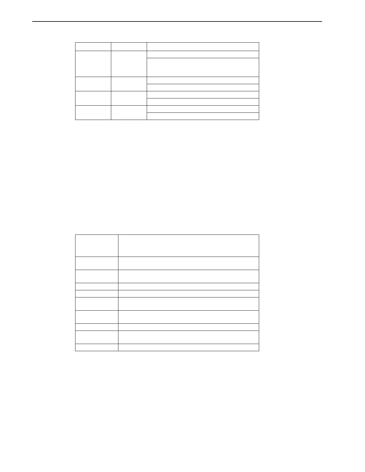
TABLE 5.1 Power Supply Module LEDs (IQ-5000 systems only)
If none of the LEDs are ON (either red or green), and incoming line voltages are found to be
correct, there may be a PSM failure. Replace the PSM with another module.
Operator Terminal
Operator Terminal Status Screens
The operator terminal has 9 status screens that may be accessed by pressing the STATUS key.
Each time the STATUS key is pressed the next status screen is displayed. The BACKSPACE key
can be used to scroll backwards through the status screens. The CLEAR Key will remove the
status display or clear the peak values. The following variables are available on status screens:
TABLE 5.2 Variables Available on Status Screens
All position values displayed on the operator terminal status screens are in user units, velocity
values are in user units per timebase, and current (torque) variables are in amps.
LED Label LED Color Description
PHASE LOSS RED OFF = OK (Normal Operation)
ON = Loss of one phase of incoming AC power.
The PSM will continue to run on two phases and
the fault LED ON.
OVERTEMP RED OFF = OK (Normal Operation
ON = Excessive main heatsink temperature
DISABLED RED OFF = Not disabled (Normal Operation)
ON = DC bus disabled by external enable input
PSM READY GREEN OFF = No DC bus voltage
ON = DC bus charged (Normal Operation
Name Description
Refer to the
IQ Master
Instruction Manual,
Part 5
•
Language
Reference for detailed information about each flag and variable
Status Flags ATHOME, HSEQCPL, INPOSN, ERROR, XFER, READY,
ENABLED, PAUSE
Program Status Program Number. If compiled with the debug option ON, the
instruction that is executing will also be displayed.
Position Status PCMD, POSN, FE
Velocity Status VCMD, FVEL1, VEL2
Input Status Inputs 1 through 16. Inputs 17 through 48 if an Expansion I/O or
Memory and Expansion I/O card is installed.
Output Status Outputs 1 through 8. Outputs 9 through 24 if an Expansion I/O or
Memory and Expansion I/O card is installed.
Current Status ICMD, IAVE, IN PEAK CURRENT
Commanded
Position Status
PGEN, PJOG, PEXT
Peak Status PFE, PVEL1, PICMD