Installation 2-15
IQ 2000/5000 Installation Manual
Operator Terminal
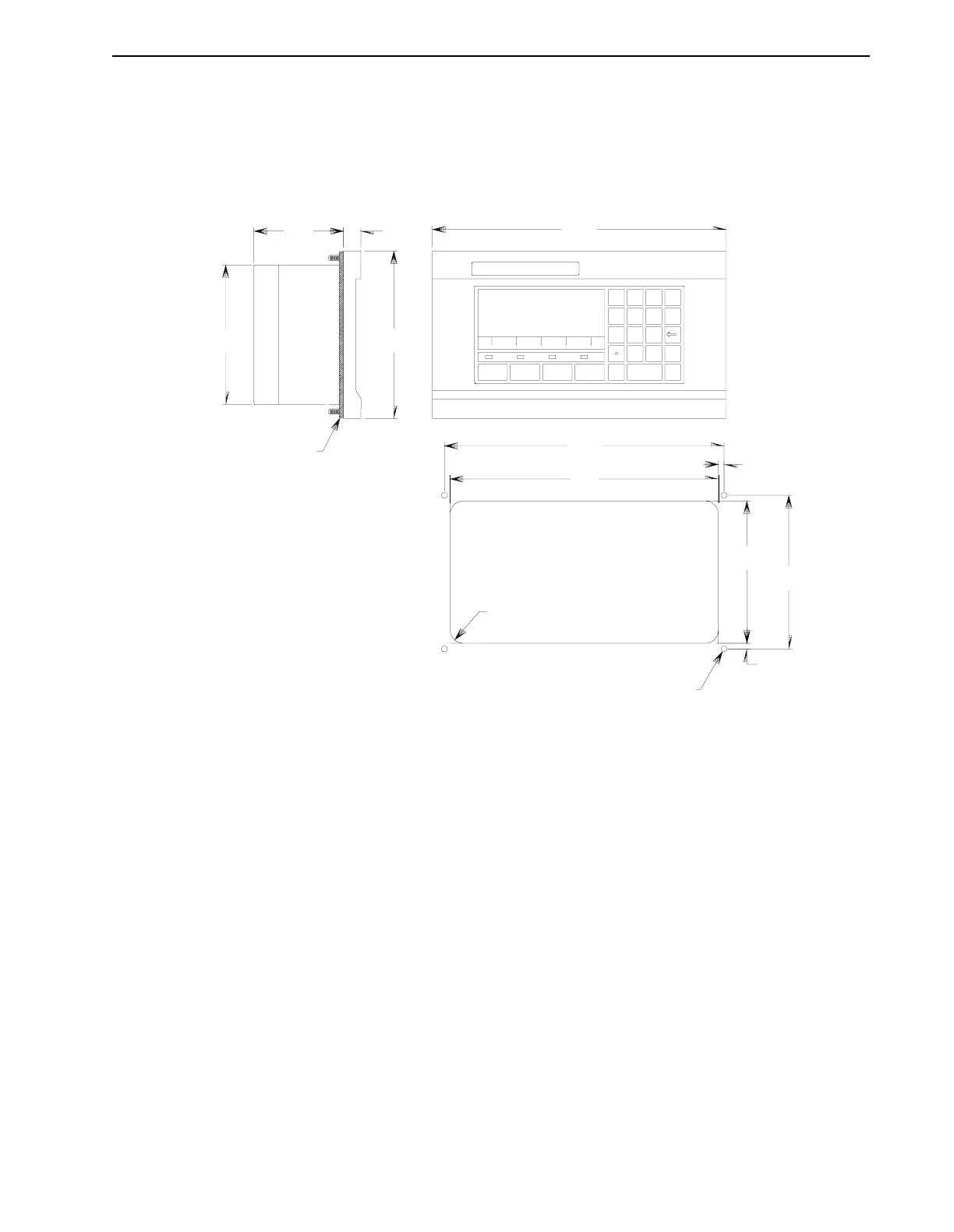
Figure 2.11 illustrates the dimensions of the Operator Terminal and the mounting panel cutout.
All dimensions are in inches (mm). Fifty millimeters (two inches) clearance above and below
the Operator Terminal should be allowed for airflow, and 100 millimeters (four inches) clearance
behind to allow for cable connectors.
Refer to “Operator Terminal” on page 6-2 for additional technical information.
FIGURE 2.11 Operator Terminal, Dimensions
0.12
[3.0]
0.62
[15.7]
6.00
[152.4]
0.203 DIA (4)
RADIUS MAX
RECOMMENDED PANEL CUTOUT DIMENSIONS
9.60
[243.8]
10.00
[254.0]
0.20
[5.1]
0.20
[5.1]
5.50
[139.7
GASKET SUPPLIED WITH UNIT
10.50
[266.7]
5.00
[127.0]
3.20
[81.3]
F4F3F2F1
X1 X2 X3 X4
0
123
456
789
DISPLAY
SYS FAULT COMM KEY
STATUS
CLE AR
ENTER
MODE
YES
NO