3-16 Wiring
P/N 0013-1027-005 Rev A
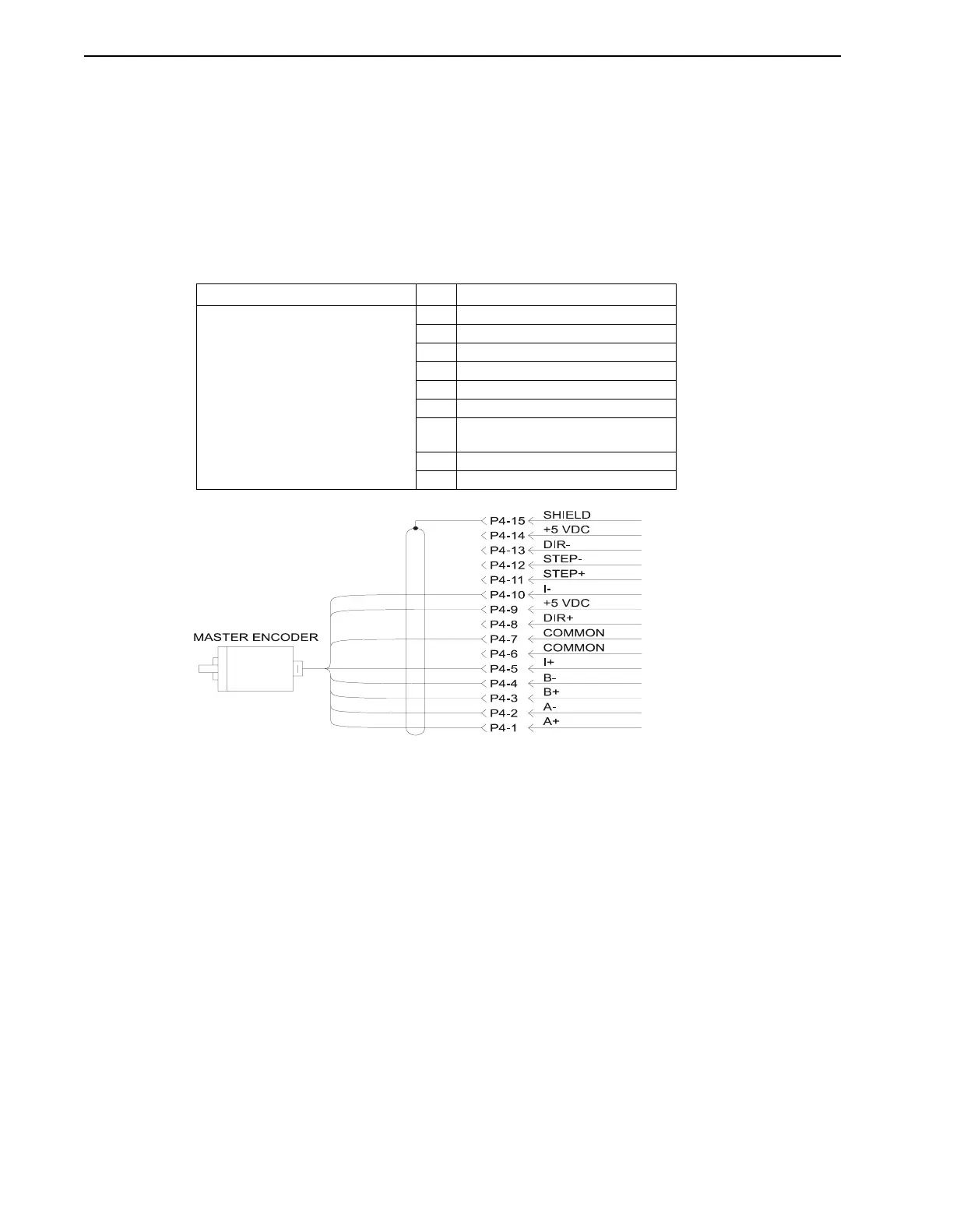
The PDM will accept differential (line driver) quadrature signals from a 5 volt incremental
encoder. The PDM accepts A, B, and I (Index) signals from the encoder, with A leading B for
clockwise rotation. Connections are provided for A+, A-, B+, B-, I+, I-, +5 volts, and common
signals. The I+ and I- signals do not need to be connected if not needed.
The Encoder 2 signal wires to the PDM should be shielded. The shield should be connected only
at the encoder end. However, in some applications it may be necessary to connect the shield at
the PDM end of the cable also. Connector P4 includes a separate pin (Pin 15) for this purpose.
Refer to Figure 3.33 on page 3-32.
TABLE 3.10 Encoder 2 and Signal Name
Slaving One IQ to Another
In applications where an IQ needs to “follow” another IQ 2000/5000 controller using electronic
gearing, the P4 connections may be used to provide a simple method of wiring the motor encoder
signals from the master IQ to the Encoder 2 input of the follower (slave) IQ. The master IQ
needs to be configured to output its motor encoder signals on P4. Refer to the IQ Master Instruc-
tion Manual for detailed information. A standard cable is available for this purpose. Refer to
Figure 3.34 on page 3-33.
Connector Pin Signal Name
P4
Encoder input 2
1A+
2A-
3B+
4B-
5 I+ (Index)
7 Common
9 +5 VDC
(250 mA maximum)
10 I- (Index)
15 Shield
FIGURE 3.14 Encoder 2 Connections