3-10 Wiring
P/N 0013-1027-005 Rev A
The IQ 2000/5000 has sinking (active low) I/O which is common in the US, but sourcing (active
high) I/O is preferred in Europe. Electro-Craft offers a DIN rail mounted interface board which
converts the I/O from sinking to sourcing (active high). This interface board must be mounted
in the same enclosure as the drive. The interface board and cables are listed below:
◆ 9103-0152
24VDC Sourcing I/O Conversion Card
◆ 44-0141-003
IQ 2000/5000 to I/O Conversion Card, 3-foot Cable
◆ 44-0141-010
IQ 2000/5000 to I/O Conversion Card, 10-foot Cable
Digital Inputs
The optically isolated inputs are connected with an internal pull-up resistor to +24 VDC. Making
a connection to the 24 volt common (closing a switch) will allow current to flow through the
opto-isolator, turning it on. In general, inputs are considered ON in this state, and OFF when
there is no connection from the input to 24 volt common. The Forward and Reverse Limit
switches are exceptions, with the switch open indicating that a limit has been hit. The Home
Switch input parameter defines the Home switch input to be open or closed to indicate the home
position, and the PAUSE parameter can select the Pause input as active open or active closed.
The general purpose inputs on the PDM are referred to as I1 through I16 in program statements.
Inputs I1 through I10 can be assigned the predefined functions shown in the table below. Inputs
I11 and I12 may be used as Interrupt inputs. Inputs I12 to I16 may be used as program select
inputs. Any of these input functions may be disabled and the inputs used as general purpose
inputs.
In addition to the input functions defined below, other functions may be assigned to any avail-
able input. Optional input functions are Hardware Reset, Kill Program, Define Home.
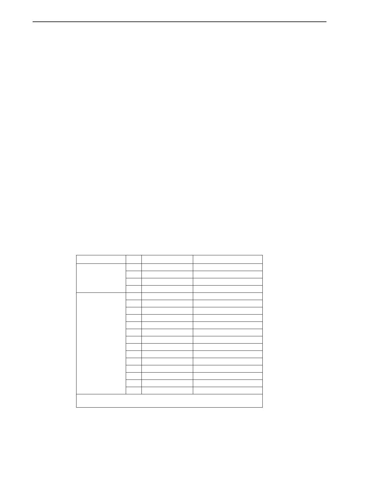
TABLE 3.2 Digital Imputs and Assignable Functions
Connector Pin Signal Name Assignable Function
P2
General purpose
inputs and outputs
12 +24 VDC
3 Input 16 (I16) Program Select MSB
2 Input 15 (I15) Program Select
1 Input 14 (I14) Program Select
P1
General purpose
inputs
14 Input 13 (I13) Program Select
13 Input 12 (I12) Int2 / Program Select
12 Input 11 (I11) Int1 / Program Select
11 Input 10 (I10) Emergency Return
10 Input 9 (I9) Pause
9 Input 8 (I8) Jog Forward
8 Input 7 (I7) Jog Reverse
7 Input 6 (I6) Home Command
6 Input 5 (I5) Home Switch
5 Input 4 (I4) Start Program
4 Input 3 (I3) Enable
3 Input 2 (I2) Reverse Limit
2 Input 1 (I1) Forward Limit
1 24 VDC Common
NOTE:
Even if an input is assigned a function, it may be used as a general purpose input.