Installation 2-17
IQ 2000/5000 Installation Manual
System Installation for Electromagnetic Compatibility
Perhaps no other subject related to the installation of industrial electronic equipment is so mis-
understood as electrical noise. The subject is complex and the theory easily fills a book. This
section provides guidelines that can minimize noise problems.
The majority of installations do not exhibit noise problems. However, the filtering and shielding
guidelines are provided as counter measures. The grounding guidelines provided below are
simply good grounding practices. They should be followed in all installations.
Electrical noise has two characteristics: the generation or emission of electromagnetic interfer-
ence (EMI), and response or immunity to EMI. The degree to which a device does not emit EMI,
and is immune to EMI, is called the device’s ElectroMagnetic Compatibility (EMC).
Equipment for use in the European Union legally requires a specific level of EMC. Since this
applies when the equipment is brought into use, it is of considerable importance that a drive
system, as a component of a machine, be correctly installed. Installation guidelines for specific
products can be found in the product manuals, or as separate documents available from Rock-
well Automation.
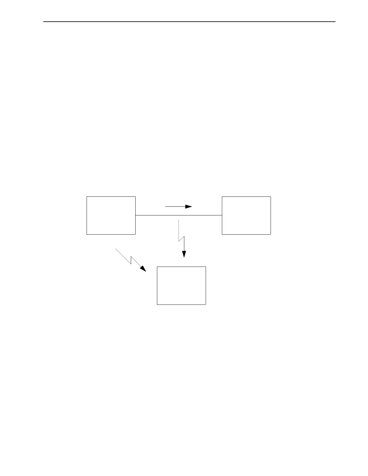
Figure 2.13 shows the commonly used EMI model. The model consists of an EMI source, a
coupling mechanism and an EMI victim. Devices such as servo drives and computers, which
contain switching power supplies, and microprocessors are EMI sources. The mechanisms for
the coupling of energy between the source and victim are conduction and radiation. Victim
equipment can be any electromagnetic device that is adversely affected by the EMI coupled to it.
Immunity to EMI is primarily determined by equipment design, but how you wire and ground
the device is also critical to achieving EMI immunity. Therefore, it is important to select equip-
ment that has been designed and tested for industrial environments. The EMI standards for
industrial equipment include EN 61000-4-X series (IEC 1000-4-X and IEC 801-X series), ANSI
C62 and C63, and MIL-STD-461. Also, in industrial environments, you should use encoders
with line driver outputs rather than single ended outputs, and digital inputs/outputs with
electrical isolation, such as those provided with optocouplers.
The EMI model provides only three options for eliminating the EMC problem:
◆ reduce the EMI at the source,
◆ increase the victim’s immunity to EMI (harden the victim),
◆ reduce the EMI at the victim (eliminate the coupling mechanism).
Intro
FIGURE 2.13 EMI Source-Victim Model
EMI
VICTIM
EMI
SOURCE
EMI
VICTIM
CONDUCTED EMI
RADIATED
EMI