3-14 Wiring
P/N 0013-1027-005 Rev A
Enabled Relay Output
The Enabled output (P3-2) is a normally open relay contact. The Enabled output closes when
the PDM is enabled, and opens when the PDM is disabled. Relay Common (P3-3) is the common
of this contact. This contact is rated 0.3 A at 24 VDC.
TABLE 3.8 Enabled Relay Output and Signal Name
Encoders
The PDM provides interfaces for two separate encoder feedback connections. The PDM will
accept encoder inputs at a maximum frequency of 750 kHz on a single channel (A or B) for
encoders with phase error of less than or equal to 45 degrees. There is a four times multiplier
on the encoder input to the PDM on both the encoder 1 and encoder 2 inputs, so four encoder
counts is equivalent to one encoder line. With a standard 2000 line encoder, the PDM will count
8000 encoder pulses per revolution.
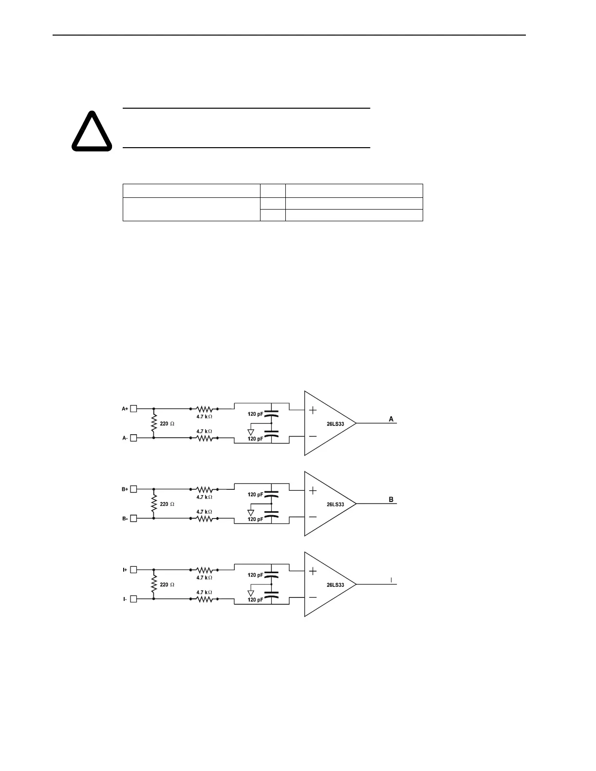
The PDM will accept differential (line driver) quadrature signals from a 5 volt incremental
encoder. As illustrated in Figure 3.12, the PDM accepts A, B and I (Index) signals from the
encoder, with A leading B for clockwise rotation facing the motor drive shaft. Connections are
provided for A+, A-, B+, B-, I+, I-, +5 VDC, and common signals.
!
WARNING: External circuitry must be used to ensure the state of
digital outputs in an emergency stop situation. The IQ 2000/5000
will
not
automatically turn outputs OFF.
Connector Pin Signal Name
P3
Analog I/O and status
2 Enabled (Relay output)
3 Relay Common
FIGURE 3.12 Encoder Input Circuitry Example