Wiring 3-13
IQ 2000/5000 Installation Manual
Analog Output
The Digital to Analog converter (DAC) output, DAC1, on pin P3-6 outputs an analog signal
with a range of ±10 volt. The analog signal ground must be connected to the Analog Common
on pin P3-4. The 12 bit DAC has a resolution of approximately 5 mV. Refer to the IQ Master
Instruction Manual for information about the use of this output.
TABLE 3.5 Analog Output and Signal Name
Monitor Output
The Programmable Monitor output allows a system variable to be monitored. The variable to
be monitored is selected in the Monitor menu, Variable Monitor Set Up dialog box. The monitor
output is a ±10 volt analog signal with 8 bit resolution. Refer to the IQ Master Instruction Manual
for information about the use of this output.
TABLE 3.6 Monitor Output and Signal Name
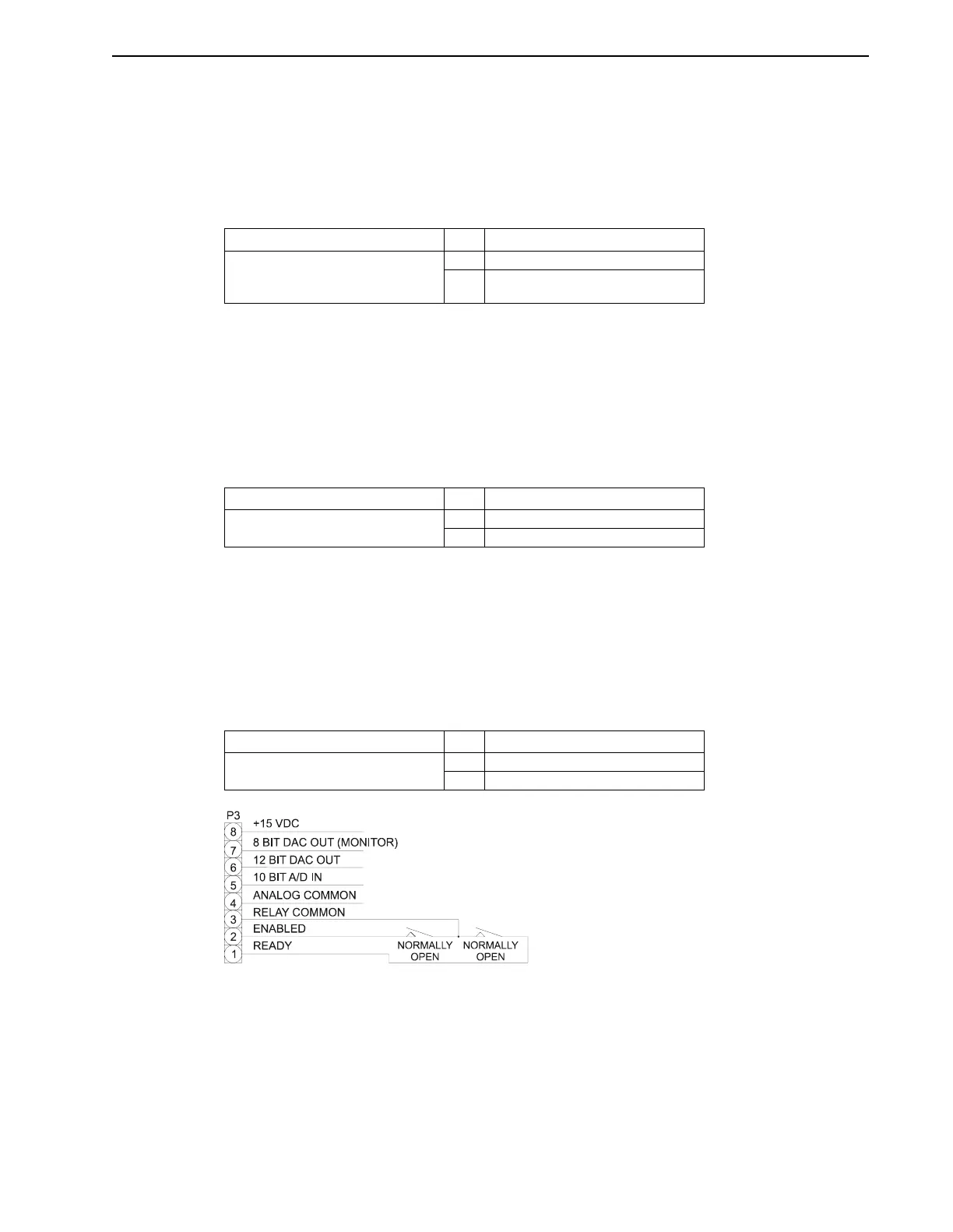
Ready Relay Output
Figure 3.11 illustrates the Ready output (P3-1), which is a normally open relay contact that closes
when the PDM is powered up if no faults exist within the PDM. Relay Common (P3-3) is the
common of this contact. This contact is rated 0.3 A at 24 VDC. The Ready output will open if a
system fault occurs.
TABLE 3.7 Ready Relay Output and Signal Name
Connector Pin Signal Name
P3
Analog I/O and
status
4 Analog Common
6 Analog Output (DAC)
Connector Pin Signal Name
P3
Analog I/O and status
4 Analog Common
7 Programmable Monitor
Connector Pin Signal Name
P3
Analog I/O and status
1 Ready (Relay output)
3 Relay Common
FIGURE 3.11 Enable and Ready Relay – Typical Internal Circuits