Bluetooth Analyzers
Page 22 of 264 | Analyzer Hardware Overviews
Capture Connector (or Primary)
The (Standard SMA) Capture connector (or Primary connector on later faceplates) is used to connect the
antenna (supplied) for capture of BR/EDR and BLE traffic, and Wi-Fi, on units configured for Wi-Fi capture. To
determine whether your Explorer is hardware-enabled for Wi-Fi and/or licensed for Wi-Fi capture, see
Section
1.6, How to Check the Analyzer’s Model, Edition.
When attaching an antenna to the front panel,
DO NOT over tighten. S
crew on
the antenna to a light finger
-tight torque only.
Generate Connector (or Secondary)
The generation function is deprecated. The (Standard SMA) Generate connector (or Secondary connector
on later faceplates) is used for Wi-Fi capture on units configured for Wi-Fi. To determine whether your Explorer
is hardware-enabled for Wi-Fi and/or licensed for Wi-Fi capture, see
Section 1.6, How to Check the Analyzer’s
Model, Edition, Features.
HCI Connectors
The HCI connectors (USB 2.0 Standard-A and Micro-B) are used for USB HCI traffic capture.
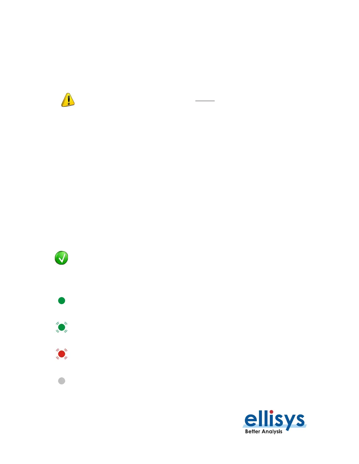
Power LED
The Power LED indicates if the unit is correctly powered from the supplied DC power adapter (or from the
battery for Vanguard units equipped with an internal battery). It also indicates whether the unit is successfully
connected to the control computer over the control connection.
Flashing LED indications on the Power LED,
the indications described below may vary
depending on whether the unit has previously initialized. With
a flashing LED of any color
, it is advised to simply remove both the USB and DC Power connections
from the back of
the unit
such that neither is attached, then reconnect them to the unit (in any order).
DC-powered and USB-connected (including USB driver properly
loaded by the
operating system)
, ready to operate.
DC-powered but not USB-connected/USB driver loaded.
USB-connected but not DC-powered
(includes cases where the USB driver does not
load
– the USB driver is in the
Drivers
folder that installs with the Ellisys Bluetooth Analyzer application)
Not DC-powered and not USB-connected. The Power LED may also be off if when the unit
-saving mode after the control computer has been turned off.
 Loading...