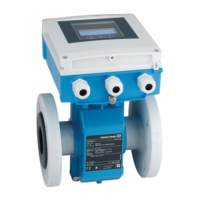
Technical data Proline Promag W 400 EtherNet/IP
136 Endress+Hauser
Installation
• Inlet run > 10 × DN
• Outlet run > 5 × DN
• Sensor and transmitter grounded.
• The sensor is centered in the pipe.
No special requirements must be observed at the inlet and outlet runs to keep within
the in-service maximum permissible errors for custody transfer.
Maximum measured error Error limits under reference operating conditions
o.r. = of reading
Volume flow
• ±0.5 % o.r. ± 1 mm/s (0.04 in/s)
• Optional: ±0.2 % o.r. ± 2 mm/s (0.08 in/s)
Fluctuations in the supply voltage do not have any effect within the specified range.
2.5
[%]
2.0
1.5
1.0
0.5
0
0.2 %
0.5 %
0
1
2 4 6 8 10 [m/s]
v
5 10 15 20 25 30 32 [ft/s]0
A0005531
32 Maximum measured error in % o.r.
2.5
[%]
2.0
1.5
1.0
0.5
0
0.2 %
0.5 %
0
10 [m/s]
v
32 [ft/s]
v
0.2
v
0.5
A0017051
33 Flat Spec in % o.r.
Flat Spec flow values0.5 %
Nominal diameter v
0.5
[mm] [in] [m/s] [ft/s]
25 to 600 1 to 24 0.5 1.64

 Loading...


