C8-B/C12-B Service Manual Maintenance Disclosure Scope: Maintenance Trained Personnel Only
(C) Seiko Epson Corporation 2-57 Rev.1
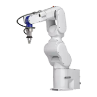
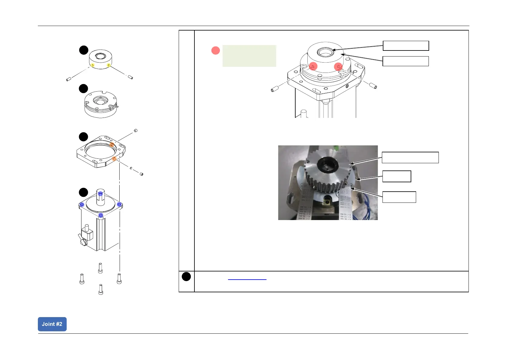
2. Secure the Motor Pulley unit to the shaft.
POINT
Place feeler gauges (0.5 mm) between the Motor Pulley and the brake, to ensure a 0.5-
mm gap during installation.
CAUTION
• Failure to create a proper gap between the Motor Pulley and the brake may cause the
parts to rub during motor operation, causing a malfunction.
• If the set screw position is incorrect, this may cause damage on the side, and may result
in not being able to remove the part.