EPSON Stylus Photo R1900/R2880/R2000/R2000s/SC-P400 Series Revision I
Adjustment Adjustment 147
8. Press the [MEASURE] button. (“----” is displayed on the LCD screen.)
9. Put the tip of the tweezers on the Drive Belt, and flip it downward in that position.
The “----” displayed on the LCD will become wave pattern during the
measurement. When it has finished, the measurement result will be displayed by
“N” (Newton) after the beep. This jig can pick up and measure sounds accurately,
regardless of the flipping force.
10. Repeating 8 and 9, delicately shift the variable part of the PF Motor mounting
position to adjust the tension until the tension falls within the allowable standard
value.
5.2.2 PG Adjustment
When any of the following parts has been removed or replaced, this adjustment must
be performed to secure the specified clearance between the print surface of the Print
Head and paper.
Print Head
Carriage Unit
Carriage Shaft
Parallelism Adjust Bushing (Including the case when just moved it)
In this adjustment, use the same Adjustment Gauge on the left and right sides.
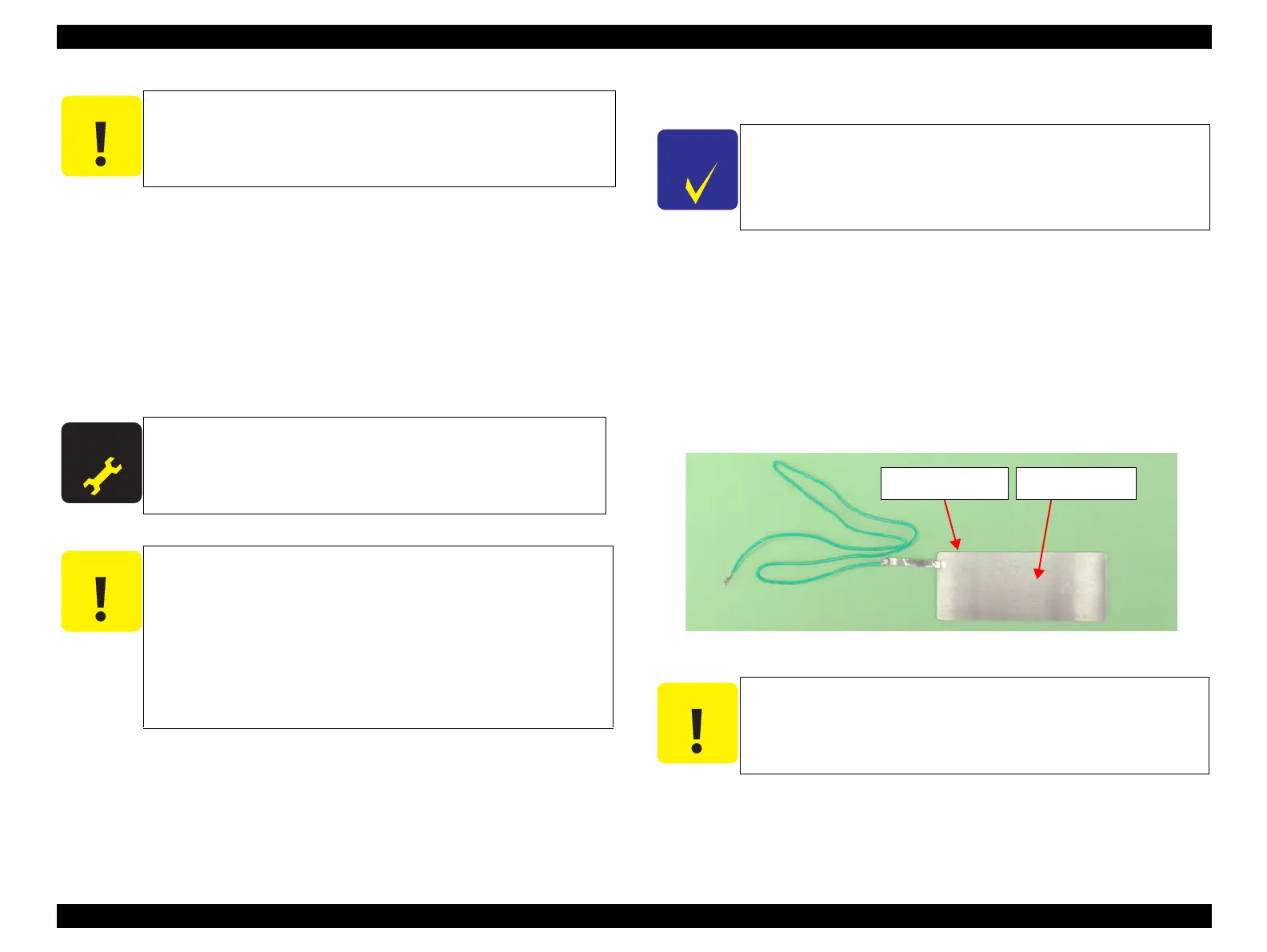
Figure 5-3. Adjustment Gauge
As the Drive Belt is flipped with the tip of tweezers in the following
steps, carefully choose the flipping position so that the Belt will not
make contact with the Microphone by reaction of flipping.
A D J U S T M E N T
R E Q U I R E D
Standard Value: 10.5 ± 2N (8.5 ~ 12.5N)
Even if the Timing Belt is flipped, the LCD screen may not
change at all. In this case, flip the Timing Belt again after a few
seconds have passed.
If measurement results differ greatly from each other, acoustic
sounds may not be picked up properly in any of the
measurements. Therefore, flip the Timing Belt again with the
tweezers, and record the value at which two measurement
results are approximate. Displaying errors in the range 1/100 to
5/100, the Measuring Tool has high reliability.
Some pictures used in this section are Stylus Photo R1800. The
adjustment method for Stylus Photo R1900/Stylus Photo R2880
is the same as the one for Stylus Photo R1800.
To change the PG position, turn the cam each on the left and
right side of the carriage shaft simultaneously.
Do not touch the Adjustment Gauge Plate surface with bare
hands.
If the Adjustment Gauge Plate surface is stained by ink or, etc.
wipe it with a soft cloth.
Continuity
Measuring Point
Adjustment Gauge
Plate (Top face)

 Loading...


