EPSON Stylus Photo R1900/R2880/R2000/R2000s/SC-P400 Series Revision I
Disassembly And Assembly Disassembling the Printer Mechanism 118
4.4.13 Ink System Unit
1. Remove the Right CDR Release Lever Sub Assy. (Refer to 4.4.12 CDR Release
Lever Sub Assy (p.116))
2. Release the Carriage Lock, and move the Carriage Unit to the center.
(Refer to 4.1.6
Locking/Unlocking the Carriage and Opening/Closing the CDR Tray Base (p.75))
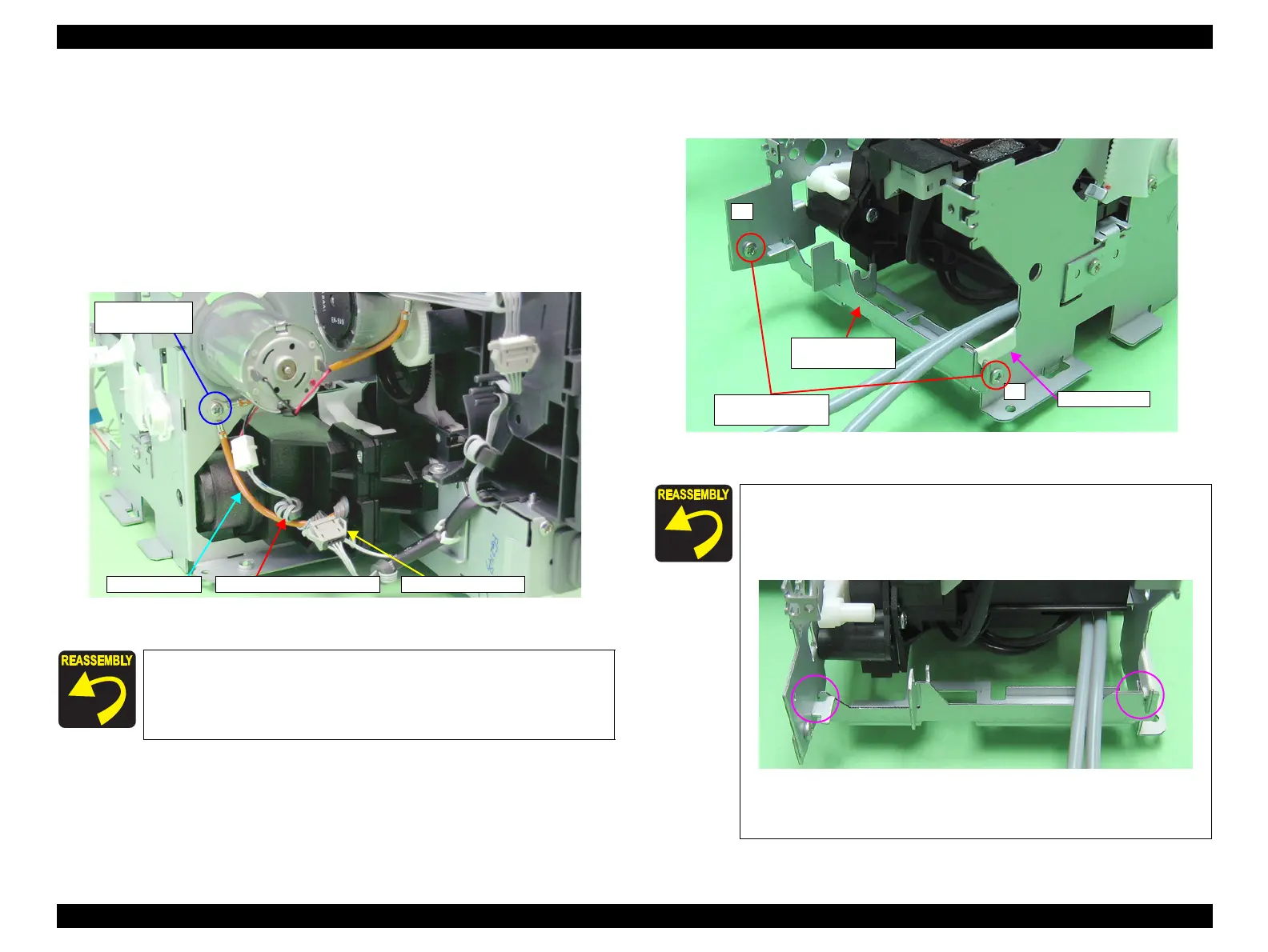
3. Remove the C.B.S. M3 x 8 screw that secures the Earth cable to remove the Earth
cables, and untie the Earth cable from the Relay connector cable.
4. Disconnect the Pump Motor connector from the Relay connector.
Figure 4-119. Disconnecting the Pump Motor Connector
5. Remove the two C.B.S. M3 x 4 screws that secure the Ink System Guide Plate, and
remove it.
Figure 4-120. Removing the Ink System Guide Plate
Be sure to screw the two Earth cables together.
Referring to Figure 4-119, correctly route the Relay connector
cable.
Relay connector
5) C.B.S. M3x8
(8±1 kgf.cm)
Earth cable
Relay connector cable
Align the notch on the Ink System Guide Plate with the notch
on the Main Frame.
Referring to Figure 4-120 and Figure 4-121, attach the acetate
tape.
Figure 4-121. Reinstalling the Ink System Guide Plate
Tighten the screws in the order shown in Figure 4-120
1
2
10) C.B.S. M3x10
(8±1 kgf.cm)
Ink System Guide
Plate
Acetate Tape

 Loading...


