EPSON Stylus Photo R1900/R2880/R2000/R2000s/SC-P400 Series Revision I
Disassembly And Assembly Disassembling the Printer Mechanism 119
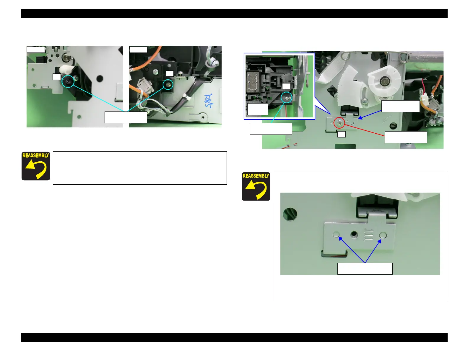
6. Remove the two C.B.S. M3 x 6 screws that secure the Ink System Unit.
Figure 4-122. Screws that Secure the Ink System Unit
7. Remove the two C.B.S. M3 x 6 screws that secure the Right Support Frame, and
remove the Right Support Frame from the Main Frame.
Figure 4-123. Removing the Right Support Frame
Tighten the screws in the order shown in Figure 4-122
2) C.B.S. M3x6
(8±1 kgf.cm)
Align the positioning holes on the Right Support Frame with
the guide pins on the Main Frame.
Figure 4-124. Installing the Right Support Frame
Tighten the screws in the order shown in Figure 4-123
2) C.B.S. M3x6
(8±1 kgf.cm)
1
2) C.B.S. M3x6
(8±1 kgf.cm)
Positioning holes and
Guide pins

 Loading...


