EPSON Stylus Photo R1900/R2880/R2000/R2000s/SC-P400 Series Revision I
Disassembly And Assembly Disassembling the Printer Mechanism 114
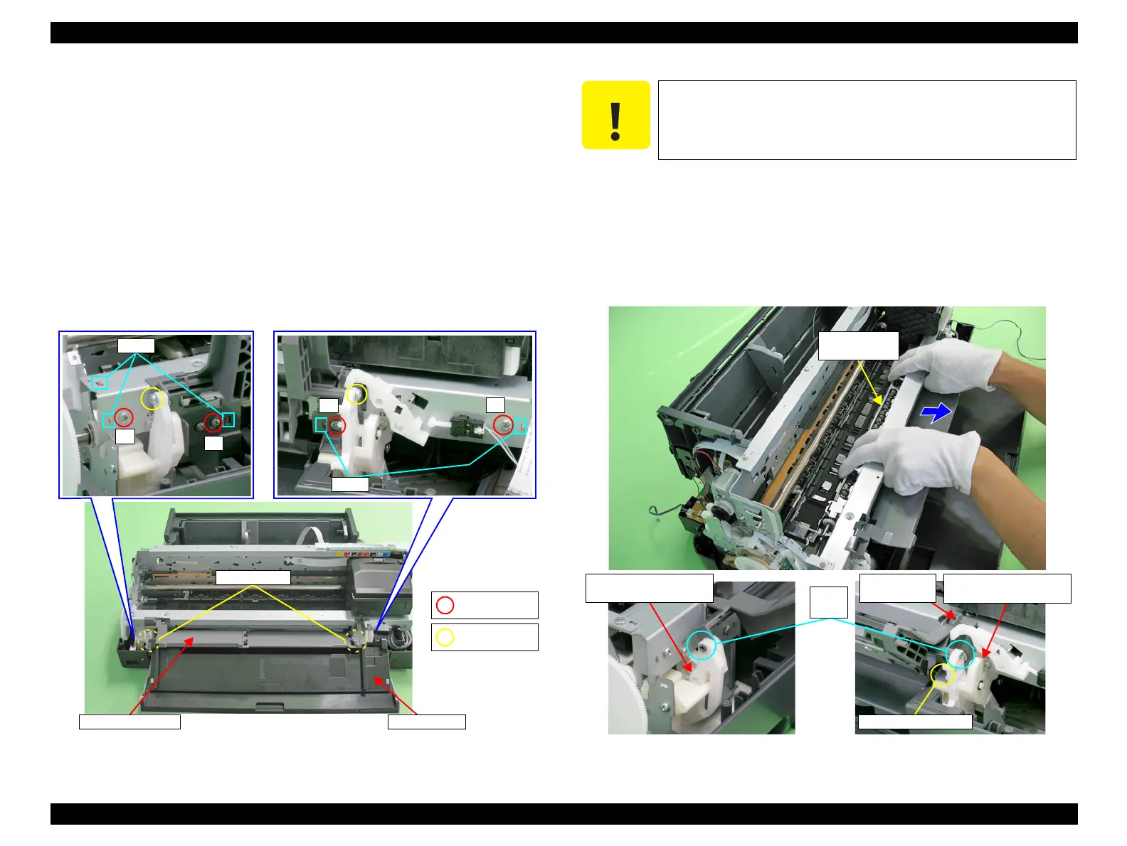
4.4.11 Paper EJ Frame Assy / Front Cover / CDR Tray
Base
1. Remove the Upper Housing Support Assy. (p.85)
2. Release the Front Cover from the two guide pins of the CDR Tray Base.
3. Release the Front Cover from the groove of the Lower Housing, and remove the
Front Cover.
4. Remove the Left Frame Support Plate. (refer to 4.4.5 Carriage Shaft / Carriage
Unit Step5 (p100), Step6(p101).)
5. Return the rotation position of the Right PG Cam.
6. Remove the four C.B.S. M3 x 6 screws and two C.B.P. M3 x 8 screws that secure
the Paper EJ Frame Assy.
Figure 4-106. Screws that Secure the Paper EJ Frame Assy
7. Remove the two guide pins on the CDR Tray Base from the Left and Right CDR
Release Lever Sub Assy.
8. Pull the Star Wheel Roller toward you, and remove the CDR Tray Base and the
Paper EJ Frame Assy from the Printer Mechanism keeping the Assy from coming
in contact with the Right CDR Release Lever Sub Assy and the tab on the Right
CDR Cover.
Figure 4-107. Removing the Paper EJ Frame Assy
2) C.B.S. M3x6
(8±1 kgf.cm)
4) C.B.P. M3x8
(8±1 kgf.cm)
When performing the following procedure, take care not to scratch
the Star Wheel.
Point of contact
Point of contact
Left CDR Release
Lever Sub Assy
Right CDR Release
Lever Sub Assy
Guide
pins
Right CDR
Cover

 Loading...


