EPSON Stylus Photo R1900/R2880/R2000/R2000s/SC-P400 Series Revision I
Adjustment Adjustment 150
9. Lower the Gear of the Parallelism Adjust Bushing on the left side of the frame
stepwise, and confirm continuity. When continuity is confirmed, define the
position where the Gear was raised one step up from the continuity position
(where continuity is lost) as the left side PG position. Move the Parallelism Adjust
Bushing at least twice to confirm that the continuity position and the non-
continuity position are the same.
10. To set the PG position to “0” or more, turn the PG Cams on right ends of the
Carriage Shaft CCW so that the point marked “0” (or “+” or “++”) faces down.
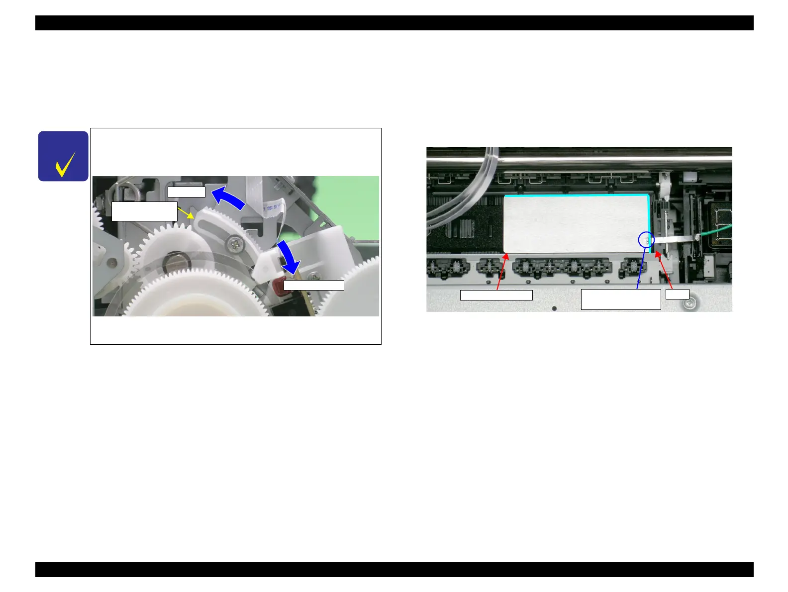
11. With its conductor connection portion up, set the Adjustment Gauge in the
specified position (on the right side of the Front Paper Guide).
Setting Position
Rear direction: Match the rear end of the Gauge with the Driven Roller Shaft
of the Upper Paper Guide.
Right direction: Release the right end of the Gauge from the Tab on the Front
Paper Guide in Figure 5-10.
Figure 5-10. Setting the Adjustment Gauge
The following figure shows the states of the Adjust Parallel Bushing
of the left side of the frame and the PG. This also applies to the
Adjust Parallel Bushing on the right side of the frame.)
Figure 5-9. Relationship between Parallelism Adjust Bushing
and PG
Narrower PG
Wider PG
Parallelism
Adjust Bushing
Setting Position
Conductor
Connection Point
Tab

 Loading...


