EPSON Stylus Photo R1900/R2880/R2000/R2000s/SC-P400 Series Revision I
Adjustment Adjustment 153
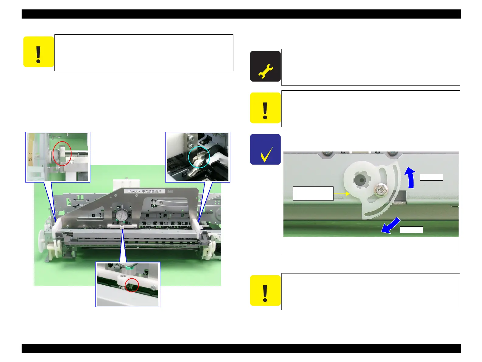
5. Set the jig in place on the PF Roller Shaft as shown in the figure below.
Left side: Inside of PF Roller left end (E-ring)
Right side: Clearance between PF Roller right end (Right Bushing 8) and left
end of Upper Paper Guide
Center: Clearance between the 2nd Upper Paper Guide and 3rd one from
the left
Figure 5-15. Setting the PF Roller Shaft Position Adjustment Jig (2)
6. Turn the Center Support Bushing Cam so that the long hand position is +30μ from
the “0” adjustment position.
7. Tighten the Center Support Bushing Cam and the Center Support Bushing with the
screws.
The following page shows print samples when adjustment of the PF Roller Shaft Center
Support Positions are inside and outside the specified value range.
Check for any dirt on the PF Roller Shaft when performing the
following procedure.
A D J U S T M E N T
R E Q U I R E D
Standard Value: 30 ± 50m
Adjustment Resolution: 50μ
+30μ must be set to compensate for the thickness of the coating
on the PF Roller Shaft.
Make sure that the position of the short hand is the same as at
“0” adjustment.
The figure below shows the positional relationship between the
Center Support Bushing Cam and the Dial Gage.
Figure 5-16. Positional Relationship between Center Support
Bushing Cam and the Dial Gage
Check the adjustment value again as it deviates slightly when the
screw is tightened.
μ down
μ up
Center Support
Bushing Cam

 Loading...


