ETEL Doc. - Operation & Software Manual # DSC2P 903 / Ver. F / 3/6/05 Chapter C: System functions
Operation & Software Manual
Direct Drives & Systems 207
Bits# 8 to 11 define the delay of synchronization of the controller:
• If bits# 8&9 = 0: the synchronization is not delayed
• If bit# 8 = 1: the synchronization is delayed of 1 [fti]
• If bit# 9 = 1: the synchronization is delayed of 2 [fti]
• If bits# 8&9 = 1: the synchronization is delayed of 3 [fti]
•...
Remark: 1 [fti] = 41.67 µs for the DSC2P/DSC2V and 1 [fti] = 55.56 µs for the DSCDP, DSCDL and DSCDP.
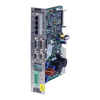
Synchronization examples:
Example at 6 kHz with a TEB communication between DSC2Ps and/or DSC2Vs:
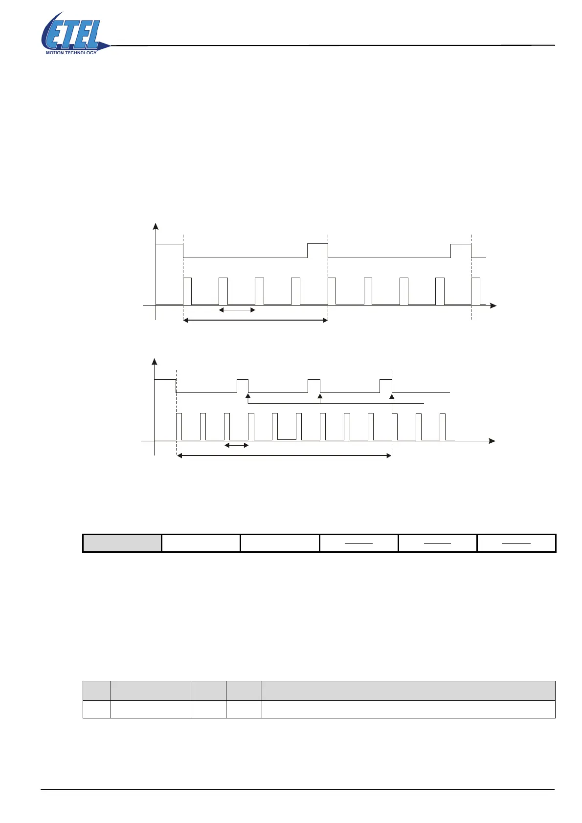
Example at 2 kHz with a TEB communication between DSCDPs or/and DSCDLs or/and DSCDMs:
13.12.2 Real-time monitoring (RTM)
13.12.2.1Slave to slave
It is possible to send two registers from a slave to another slave through a real-time monitoring channel. To do
so, a DSMAX or a DSTEB must be present as a master of the communication ring and the following parameters
set (this function is then not available with a DSC2P or DSC2V in µ-master mode). There can be a maximum
of 4 slaves sending 2 registers to other slaves through 4 real-time monitoring channels.
Warning: A slave must not receive registers trough the real-time monitoring channel from more than one
slave.
To activate the desired RTM mode, parameter K102 must be correctly set:
To enable the slave to slave mode, parameter K102 must be equal to 2 (bit 1 set) or 3 (bits 1 & 2 set).
Available on DSC2P DSC2V DSCDP DSCDL DSCDM
K Name Value Bit # Comment
K102 RTM channel mode 2 1 Enables the slave to slave communication mode
1 [fti]
1 [sti]
DSC2P
internal
interrupts
TEB
synchro
Synchro
signal
Synchro
signal
Synchro
signal
re-synchronization
1 [fti]
1 [sti]
DSCDx
internal
interrupts
TEB
synchro
Synchro
signal
Synchro
signal
re-synchronization
 Loading...
