ETEL Doc. - Operation & Software Manual # DSC2P 903 / Ver. F / 3/6/05 Chapter E: Appendixes
Operation & Software Manual
Direct Drives & Systems 295
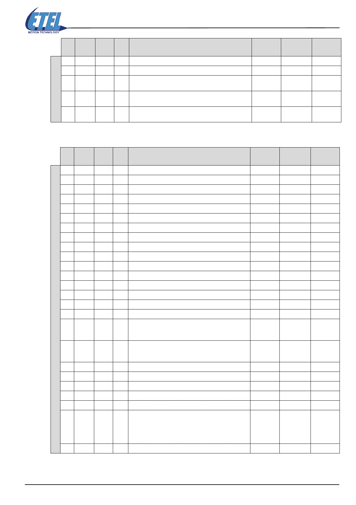
16.3 Parameters K for DSCDL
DSCDP parameters
3 Real sine movement
K240 Motor type. 0: linear motor, 1:rotary motor 0 0 1
K241
Encoder period in [nm] for linear encoder or number of
period for rotary encoder
1 -2147483648 2147483647
K242
Position multiplication factor (is used by the DLL to
calculate the position unit with indirect encoder)
1 1 2147483647
K243
Position division factor (is used by the DLL to calculate
the position unit with indirect encoder)
1 1 2147483647
K Alias
Val
<P1>
Bit #
<P1>
Comment for parameters K
and <P1> of the DSCDL
Def. Val
<P1>
Min. Val
<P1>
Max. Val
<P1>
DSCDL parameters
K1 Position loop proportional gain 100 0 2147483647
K2 Position loop speed feedback gain 20 0 2147483647
K3 Position loop force feedback gain 0 0 2147483647
K4 Position loop integrator gain 0 0 2147483647
K5 Position loop anti-windup gain 10 0 2147483647
K6 Position loop integrator limitation 1073741823 0 2147483647
K7 Position loop integrator mode 0 0 2
0 Position loop integrator gain (K4) always on
2 Position loop integrator gain (K4) always off
K8 Position loop speed filter 0 0 511
K9 Force reference filter on the position regulator output 0 0 511
K11 Speed smooth filter for TTL encoder 0 0 256
K20 Position loop speed feedforward gain 0 0 2147483647
K21 Position loop acceleration feedforward gain 0 0 2147483647
K23 Commutation phase advance according to the speed 0 0 65535
K27 Maximum position range limit for rotary movement 1 0 2000000000
K30
Absolute tracking error limit. When the tracking error is
greater than K30, the controller generates the error
M64=23
10000000 0 1073741823
K31
Absolute velocity limit. When the velocity is greater than
K31, the controller generates an overspeed error
M64=24
100000000 0 2147483647
K32 Limit switch and home switch inversion 0 0 47
1 0 Enables the use of the limit switches
2 1 Inverts home switch
4 2 Inverts limit switches from the encoder
8 3 Inverts limit switches
32 5
Enables limitation of K60/K31 according to DIN. K178:2
defines the mask of the DIN that should be at 1 to limit
K60 and K31. K179:2 defines the mask of the DIN that
should be at 0 to limit K60 and K31. K60:3 and K31:3 are
the limitation
K33 Enables input mode 125 0 125
K Alias
Val
<P1>
Bit #
<P1>
Comment for parameters K
and <P1> of the DSCDP
Def. Val
<P1>
Min. Val
<P1>
Max. Val
<P1>
 Loading...
