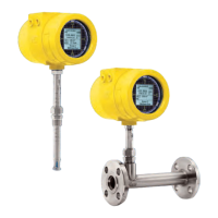
INSTALLATION ST80/ST80L Flow Meter
12 Fluid Components International LLC
ST80L In-Line Process Connection
The in-line ST80L flow element assembly can be threaded, flanged or butt weld mounted to the process piping. The specific type in-line process
connection is customer-specified on the order information sheet (OIS). See Figure 7 below.
Mount the sensor to the process piping per the application piping requirements. Verify the flow direction arrow is pointed in the correct direction. After
the sensor head has been located correctly and tightened into place, verify the process seal does not leak by slowly applying pressure until the
normal operation pressure is applied. Check for leaks at the process connection boundary.
Figure 7 – ST80L Process Connection
Flow Transmitter Electronics Installation
The instrument electronic transmitter can be an integral part of the flow element or it can be mounted remotely using a shielded cable between the
flow element and the electronics.
Use power wiring with a minimum 90 °C rating.
ESD Precautions
FCI flow meters contain static-sensitive devices. To avoid damage to the instrument observe the ESD precautions
listed below before opening the instrument for wiring.
● Use a wrist band or heel strap with a 1 MΩ resistor connected to ground.
● Use a static conductive mat on the work table or floor with a 1 MΩ resistor connected to the ground when working on the instrument in
a shop setting.
● Connect the instrument to ground.
● Apply antistatic agents such as Static Free made by Chemtronics to hand tools used on the instrument.
● Keep high static-producing items away from the instrument.
The above precautions are minimum requirements. The complete use of ESD precautions can be found in the U.S. Department of Defense
Handbook 263.
C00993-2-1
LINE SIZE "A" LENGTH
1" 9"
1½" 13.5"
2" 18"
FLOW DIRECTION
OPTIONAL
CUSTOMER
PROCESS
CONNECTIONS
BUTT WELD FEMALE NPT MALE NPT
OPTIONAL VORTAB
2x FLANGED
PROCESS CONNECTION
7x DIA. 2x DIA.

 Loading...