INSTALLATION ST80/ST80L Flow Meter
26 Fluid Components International LLC
FOUNDATION Fieldbus/PROFIBUS Configuration
Refer to Figure 16 on page 19. To set J8 for FF/PROFIBUS operation install a 2 mm jumper shunt onto the J12 and J13 jumper pins as
shown in Table 5 below.
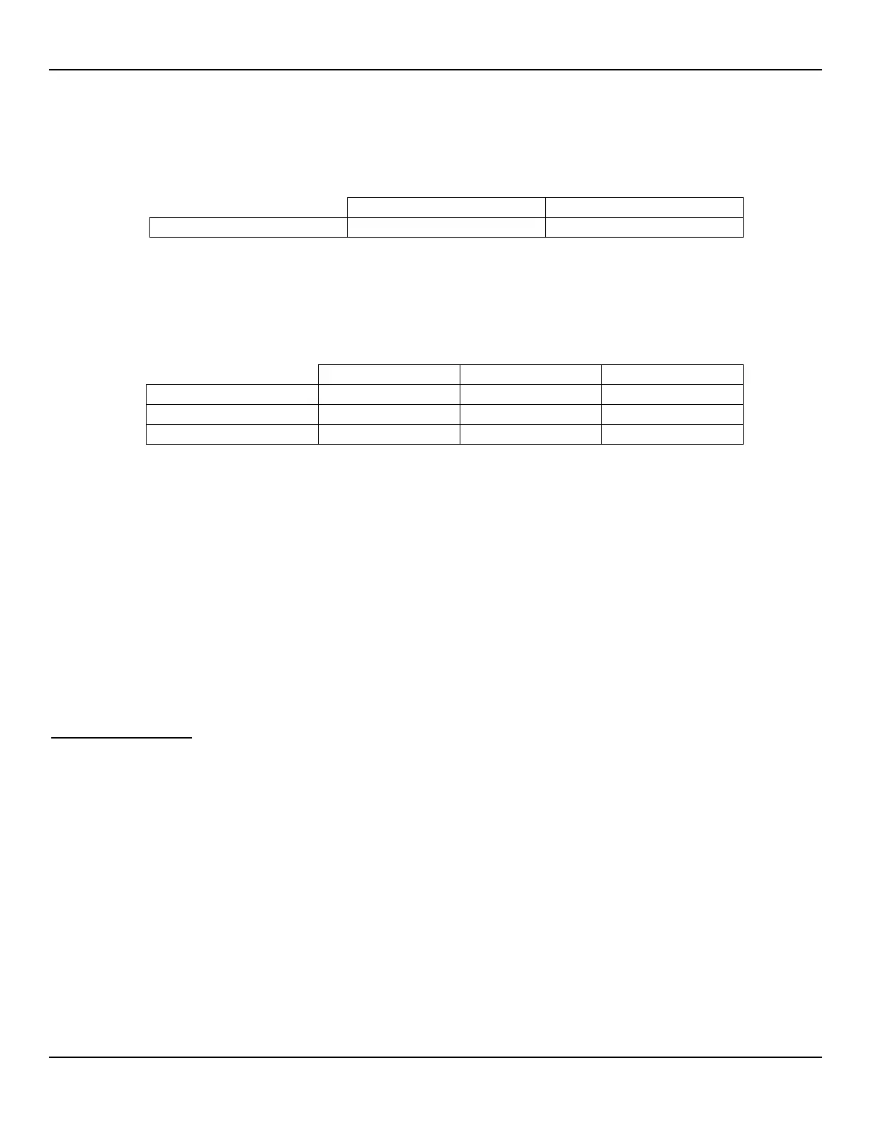
Table 5 – FOUNDATION Fieldbus/PROFIBUS Select Jumpers
Install Jumper Shunt over Pins
As required for your application set 2 mm jumper shunts as needed to configure the bus lines as listed in Table 6 below. Termination is
typically required for applications with faster data rates or long cable lengths or both. Enable the instrument’s terminator as required for
your application. Line biasing is used to ensure that lines are at a known state (noise can cause a false trigger on a floating line). Check
first that the RS-485 network is not already biased before enabling the ST80/ST80L line biasing.
Table 6 – FOUNDATION Fieldbus/PROFIBUS Line Configuration Jumpers
Note: 1. ● = Jumper Installed
F
OUNDATION Fieldbus/PROFIBUS Add-On Card Diagnostics/Test
As shown in Figure 16 on page 19 a mini-DIP switch (use push pin or ballpoint pen to actuate) controls the optional Fieldbus/PROFIBUS
add-on card’s #SIM_ENABLE, #NV_ERASE, and #HW_LOCK test signals. This provides a means to activate a “simulate mode” for
Fieldbus conformance testing and for add-on card testing/diagnostics. A particular signal is active when its switch is set to ON. For normal
use all switches are OFF.
Service Port Connection, USB
The ST80/ST80L is provided with a USB service port that is used to configure/monitor the instrument via a PC. Refer to Configuring the
ST80/ST80L, page 27 for further information on service port use.
● USB 2.0 – USB Type B connector J21 on the main board (for local connection of PC to the instrument)
Post Installation Check
Verify all wiring connections are secure and correct to the appropriate wiring diagram. Verify the flow direction arrow on the flow element is pointing
in the right direction. Verify the mechanical process connection is secure and meets the system pressure requirements.

 Loading...


