ST80/ST80L Flow Meter OPERATION
Fluid Components International LLC 65
Modbus Operation
The ST80/ST80L offers Modbus as one of its digital communication protocol, but unlike the other digital communication protocols Modbus
only offers set up and configuration for the totalizer variable. Refer to Modbus Connections on page 24 for Modbus wiring info.
The ST80/ST80L Modbus physical layer uses the flow meter’s asynchronous RS-485 serial port. There is no high speed Modbus over
Ethernet. The ST80/ST80L offers the two basic traditional transmission serial interface modes: RTU and ASCII message coding.
The ST80/ST80L offers the process variable parameters (value) in floating point form, which are organized as single or double precision
floating point registers. These registers are the 4000 and the 5000 group registers, both of which are accessed using Modbus 03 and 04
function codes. Refer to Table 20, page 67, for an overview of the registers.
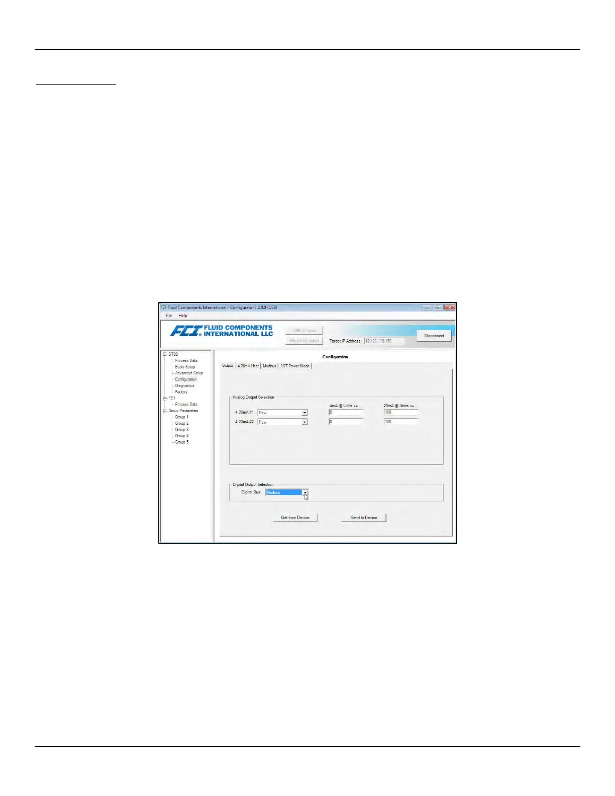
Setting the ST80/ST80L for Modbus Operation
The ST80/ST80L Configuration Software application is used to select the instrument’s digital communication protocol.
Using the supplied USB cable, connect the instrument’s USB port to a USB port on the PC running the configurator software.
Launch the ST80/ST80L Configurator (with the PC already connected to the instrument). Select Configuration branch from the menu tree
on the window’s left side. Observe that the Output tab is selected. In the window’s Digital Output Selection field, check whether or not
Modbus is shown for Digital Bus. If not, use the Digital Bus pulldown menu to select Modbus. Then click Send to Device to program the
ST80/ST80L (enter “2772” user password).
Figure 48 – ST80/ST80L Configuration Software Output Tab with Modbus Selected
Click the Modbus tab and configure the serial interface parameters (Node ID, Mode, Baud, Data Bits, Parity, and Stop Bits) as required for
your application. Then click Send to Device to program the ST80/ST80L (enter “2772” user password). Refer to the ST80/ST80L
Configuration Software manual 06EN003491 for details on configuring the digital bus and using the software.