ST80/ST80L Flow Meter INSTALLATION
Fluid Components International LLC 21
Power overload protection is provided by a clip-mounted SMT fuse. Refer to Power Fuse Replacement, page 76 (MAINTENANCE section)
for fuse replacement details.
Flow Element Connections
The flow element in all integral units is pre-wired at the factory. The information in this section applies to remote
configuration units only.
See the appropriate wiring diagram in APPENDIX A for interconnect wiring between the flow element and remote electronics. Use an 8-
conductor shielded cable for the external flow element input. The flow meter will not operate properly without these connections. To avoid
inaccurate flow meter readings make sure the ACT and REF wires are not reversed.
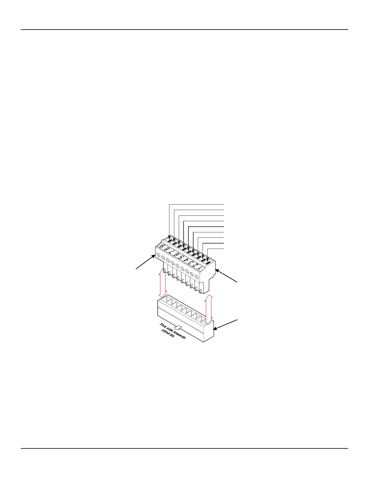
Referencing Figure 14 connect the ST80/ST80L flow element sensor wires to the detachable 9-position connector plug TB1 on the main
board. See Figure 19 below. The connector plug accepts 28-16 AWG (0.14 mm
2
- 1.5 mm
2
) wire (refer to Table 2, page 17 for wire size vs.
length info). Connect the flow element cable shield to the connector plug’s GND terminal (terminal #9). Leave the other end of the shield
floating (no connection to the flow element enclosure).Connect the flow element sensor to the plug as follows:
1. Remove connector plug from board (pull straight out).
2. Route sensor wires through remote enclosure’s wiring port/cable gland. Refer to Figure 13, page 17.
3. Strip wire ends (0.27 in [7 mm]) and insert into appropriate plug terminals as shown in Figure 19 below. Make sure to tighten each
terminal screw securely (max. torque: 2.2 inch-lbs [0.25 N-m]).
4. After all terminations are made plug connector block back into its header socket on the board.
Figure 19 – Flow Element Connections, TB1
C01431-1-1
1. HTR EXC #1
2. HTR RTN
3. ACT EXC
4. ACT SEN
5. GND SEN
6. GND
7. REF EXC
8. REF SEN
9. SHIELD

 Loading...


