ST80/ST80L Flow Meter INSTALLATION
Fluid Components International LLC 7
2 INSTALLATION
● Consult the manufacturer if dimensional information on the flameproof joints is necessary.
● The ambient temperature range and applicable temperature class of the ST80/ST80L flow meter is based on the
maximum process temperature for a particular application. Refer to page 139 for details.
● The painted surface of an ST80/ST80L flow meter (aluminum housing only) can store electrostatic charge and become
a source of ignition in applications with a low relative humidity < 30% relative humidity where the painted surface is relatively
free of surface contamination such as dirt, dust, or oil. Clean painted surfaces using a damp cloth moistened with water only.
● Do not replace internal battery when an explosive gas atmosphere is present.
Instrument Identification and Outline Dimensions
APPENDIX A starting on page 91 provides outline dimensions and mounting bracket dimensions for all integral and remote mounted electronic
configurations. Verify all dimensions meet the application requirements before beginning the installation process.
ST80 Insertion Sensor Installation
The proper flow meter location in the process piping configuration is critical to the instrument’s ability to measure the process variables accurately.
FCI recommends 20 nominal pipe diameters upstream and 10 pipe diameters downstream of the instrument installation point for most applications.
These distances can be significantly reduced when the flow meter is combined with FCI’s flow conditioning technology (Vortab).
Insertion flow elements can be mounted into the process using several available customer selectable configurations; compression fitting mounted,
threaded or flanged packing gland mounted, and threaded or flanged fixed “U” length mounted process connections. The specific sensor process
connection is specified by the customer on the order information sheet (OIS).
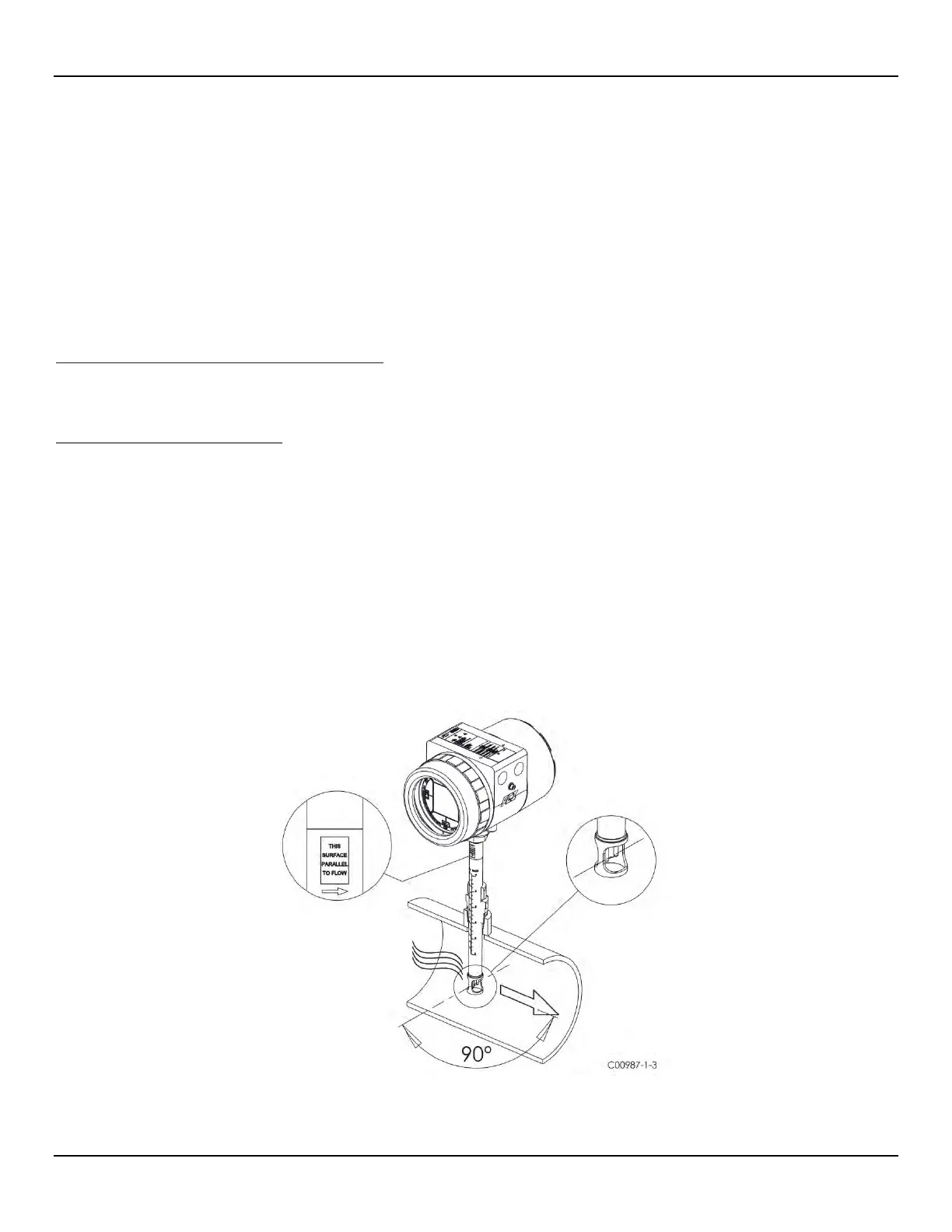
Mount the flow element to the process piping per the application piping requirements. Orient the instrument so that the flow arrow etched on the
element matches the direction of the process flow with the reference flat parallel to flow within ±3° of rotation. Insert a flow element with variable
insertion length ½” inch past the centerline of the process pipe or tube with the flow direction arrow correctly aligned and leveled. After the flow ele-
ment has been located correctly and tightened into place, verify that the process seal does not leak by slowly applying pressure until the maximum
operation pressure is applied. Check for leaks at the process connection boundary using standard leak detection methods.
Figure 1 below shows a properly mounted compression fitting process connection instrument.
Figure 1 – Example Compression Fitting Process Connection

 Loading...


