ST80/ST80L Flow Meter TROUBLESHOOTING
Fluid Components International LLC 83
Verification of the Electronics
Explosion Hazard. Do not disconnect equipment when flammable or combustible atmosphere is present. Operator
assumes responsibility for all safety concerns relating to interrupting and reapplying power to their instrumentation.
The information in this section applies to both AST™ and Constant Power configured instruments.
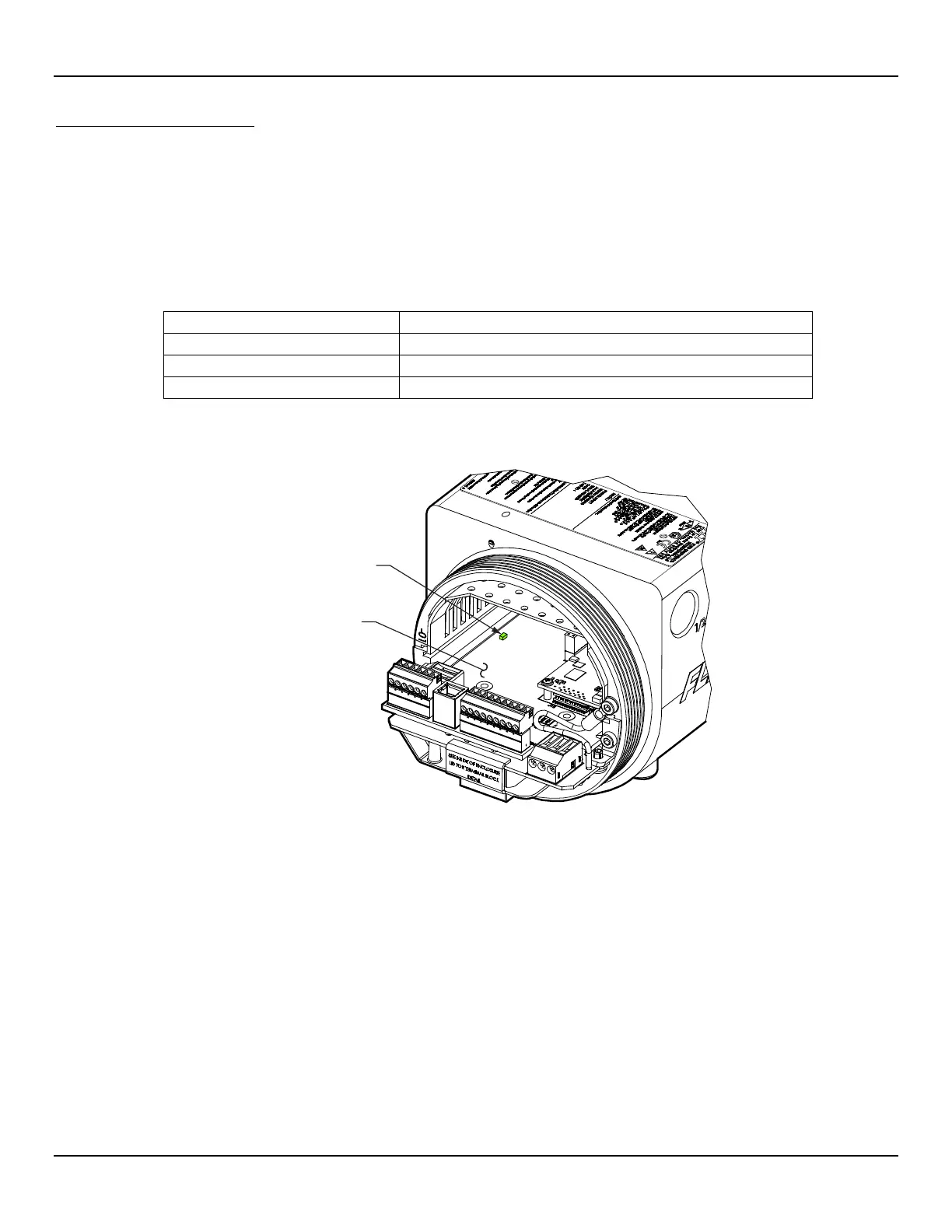
With instrument power ON remove the instrument’s blind lid (see Accessing the I/O Connectors, page 18). Check the green system status
LED on the main board (see Figure 60 below). The system status LED states are listed in the table below.
Table 30 – System Status LED D3 States
System Status LED (D3), State
Slow blink (blink every 2 seconds)
No power or power supply issue, or system controller halted (hang).
ON (no blink, continuous)
System controller halted (hang).
Cycle the power to see if the instrument recovers from a possible system controller hang. Contact FCI Technical Support for assistance if the
system status LED is still not blinking.
Figure 60 – System Status LED, Main Board
After checking the system status LED, verify the electronics with the three checks summarized below (there is no sequence in performing
these checks).
Transmitter Power Supply Check via configuration software: Factory|Sil Adj tab (see Transmitter Power Supply, below). Make sure
that the displayed power supply voltages are within range.
Heater Check via configuration software: Diagnostics|Heater Values tab (see Check the Heater, above). Make sure that the heater
resistance, voltage, and current are within range.
Internal Delta-R Resistor (idR) Check via HMI display or configuration software: Diagnostics/idR Scheduled Tests tab (see Internal
Delta-R Resistor (idR) Check, page 39). After running the idR check, verify that the Low, Mid, and High range values show “Passed.”
Should any of these checks fail, contact FCI Technical Support for assistance.