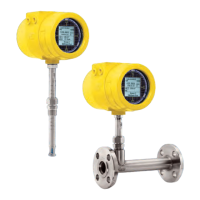
ST80/ST80L Flow Meter 06EN003490 Rev. B
Fluid Components International LLC v
List of Figures
Figure 1 – Example Compression Fitting Process Connection ................................................................................................................. 7
Figure 2 – Compression Fitting Installation, Dimensions .......................................................................................................................... 8
Figure 3 – Example Flange Mount Installation .......................................................................................................................................... 9
Figure 4 – Example NPT Pipe Thread Mount Installation ......................................................................................................................... 9
Figure 5 – Retractable Packing Gland Installation .................................................................................................................................. 10
Figure 6 – Packing Gland Locking Collar ................................................................................................................................................ 11
Figure 7 – ST80L Process Connection ................................................................................................................................................... 12
Figure 8 – Integral Electronics Installation (Compression Fitting Shown) ............................................................................................... 13
Figure 9 – Remote Installation, Mounting Bracket on Wall ..................................................................................................................... 14
Figure 10 – Remote Installation, Mounting Bracket on 1" – 1½" Pipe .................................................................................................... 15
Figure 11 – Remote Installation, Mounting Bracket on 2" Pipe ............................................................................................................... 15
Figure 12 – Remote Installation, Optional Stainless Steel Bracket on 2" Pipe ....................................................................................... 16
Figure 13 – Recommended Wiring Routing, Base Electronics Enclosure .............................................................................................. 17
Figure 14 – ST80/ST80L I/O Connector Locations ................................................................................................................................. 18
Figure 15 – ST80/ST80L Electronics Enclosure Label ........................................................................................................................... 19
Figure 16 – Bus Configuration 2 mm Jumper Headers and DIP Switch ................................................................................................. 19
Figure 17 – Input Power Wiring .............................................................................................................................................................. 20
Figure 18 – ST80/ST80L Ferrite Core Installation .................................................................................................................................. 20
Figure 19 – Flow Element Connections, TB1 ......................................................................................................................................... 21
Figure 20 – HART and Ch. 1 & Ch. 2 4-20 mA Connections, J25 .......................................................................................................... 22
Figure 21 – Single Connection and Multidrop HART Setups .................................................................................................................. 23
Figure 22 – Modbus/PROFIBUS/Fieldbus Connections, J8 ................................................................................................................... 24
Figure 23 – Modbus Wiring ..................................................................................................................................................................... 24
Figure 24 – Fieldbus/PROFIBUS Wiring ................................................................................................................................................. 25
Figure 25 – Hot Key on the Optional HMI Display .................................................................................................................................. 27
Figure 26 – HMI Display IR Sensor Functions ........................................................................................................................................ 28
Figure 27 – Basic Setup Options, HMI .................................................................................................................................................... 29
Figure 28 – Instrument Setup Options .................................................................................................................................................... 29
Figure 29 – Display Setup Options ......................................................................................................................................................... 30
Figure 30 – Configuration Software Tabs for Basic Setup Functions ..................................................................................................... 31
Figure 31 – Example Log, Alarm, and Logging Icons on the Optional Display ............................................................................................... 32
Figure 32 – The Configurator Welcome Screen ..................................................................................................................................... 32
Figure 33 – Example Process Data Screen ............................................................................................................................................ 33
Figure 34 – Example Date and Time Set Screen ................................................................................................................................... 33
Figure 35 – Example Totalizer Display Showing Total Flow Value ......................................................................................................... 34
Figure 36 – Totalizer Setup Screen ........................................................................................................................................................ 34
Figure 37 – Example AST Power Mode Tab (Configuration) .................................................................................................................. 35
Figure 38 – Flow Filtering Setup Screen ................................................................................................................................................. 36
Figure 39 – Chart: Flow Output Over Time with Various Flow Damping Values .................................................................................... 37

 Loading...