INSTALLATION ST80/ST80L Flow Meter
18 Fluid Components International LLC
Accessing the I/O Connectors
Turn instrument power OFF before wiring the instrument.
Use caution inserting wires into electronics housing. The metal ends can damage circuit boards.
Remote Units: Avoid pulling, or inadvertently tugging, the remote cable when wiring the instrument. The sensor
connector/circuit board can be easily damaged by excess pulling of the remote cable.
Observe ESD precautions when wiring the instrument. Refer to ESD Precautions, page 12.
To access the instrument’s connection terminals first use a .050″ hex key to loosen the set screw locking the enclosure body blind lid. Then
unscrew the blind lid from the enclosure. Carefully pull the power and signal wires through the port to avoid damaging the electronics.
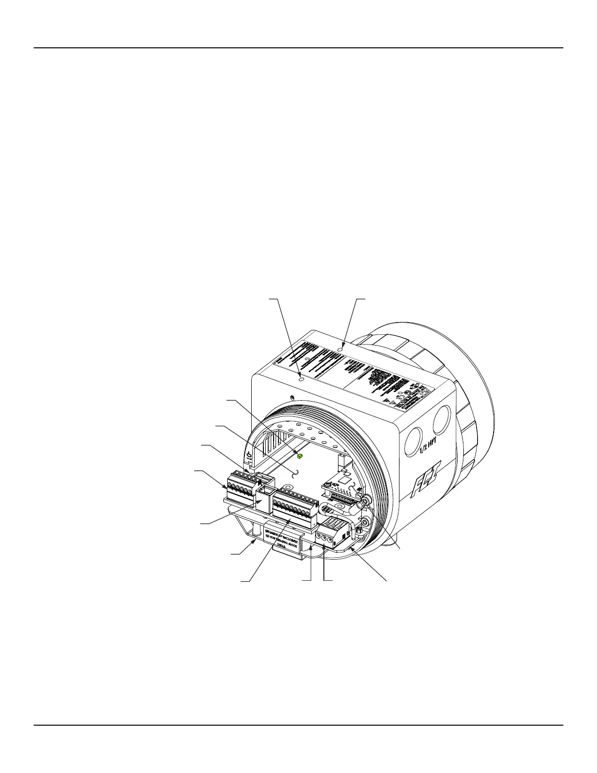
Figure 14 below shows the location of the ST80/ST80L I/O connectors as well as the lid set screw access holes in the enclosure body.
Connect wiring as described in the following paragraphs. Reinstall the blind lid when done making the connections: Tighten the lid one full
turn past the point where the O-ring makes contact with the lid, and then tighten the lid set screw to lock the lid (set screw must not
protrude from its threaded hole after tightening).
Figure 14 – ST80/ST80L I/O Connector Locations
BLIND LID
LOCKING SET SCREW
WINDOW LID
LOCKING SET SCREW
USB TYPE B (PC CONFIG),
J21
PROFIBUS
4-20 mA CH. 2 OUT,
Modbus/PROFIBUS/Fieldbus,
J8

 Loading...


