INSTALLATION ST80/ST80L Flow Meter
24 Fluid Components International LLC
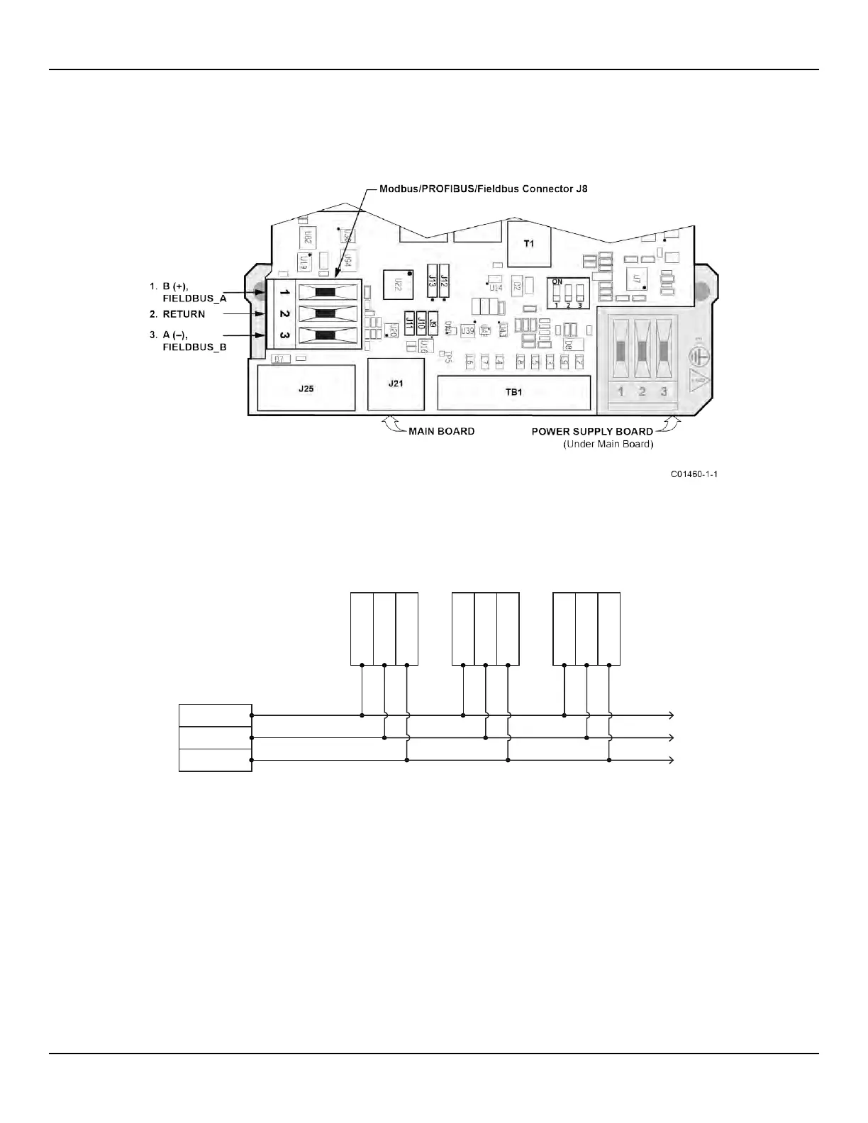
Modbus Connections
Referencing Figure 14 connect the Modbus device/network to Phoenix connector J8 on the main board. Note that the J8 connector is also
used for F
OUNDATION Fieldbus and PROFIBUS wiring (only one interface can be active at a time). See Figure 22 below. Connector J8
accepts 24–12 AWG (0.2 mm
2
– 1.5 mm
2
) wire (refer to Table 2, page 17 for wire size vs. length info).
Figure 22 – Modbus/PROFIBUS/Fieldbus Connections, J8
Connect the ST80/ST80L to a Modbus device/network using a 2-wire RS-485 connection scheme as shown in Figure 23 below. For details
on Modbus operation refer to Modbus Operation, page 65.
Figure 23 – Modbus Wiring
RS-485 MASTER
2-WIRE ONLY DEVICE
DEVICE 1 DEVICE 2 DEVICE 3
One twisted wire pair
plus Gnd/Common.
To remaining
RS-485 Devices
DATA (B)+
DATA (A)-
GND
DATA (B)+
DATA (A)-
GND
DATA (B)+
DATA (A)-
GND
DATA (B)+
DATA (A)-
GND
C01415-1-1

 Loading...


