ST80/ST80L Flow Meter TROUBLESHOOTING
Fluid Components International LLC 85
Constant Power Configuration Troubleshooting
Equipment List
● 250 Ω 0.01% resistor
● 2 digital multimeters (DMM)
● Delta R Calibration Data Sheet (serial number specific by instrument and group)
● FES-200 flow element simulator
● FES-200 interface cable for ST80/ST80L (022610-xx)
Alternative to FES-200:
● 2 ea. Precision Decade Resistance Box, 0.1% (1 kΩ large step, 0.01 Ω small step)
Delta R Check for Constant Power Configured Units
If the flow meter’s parameters have been changed, calibrations may be inaccurate or factory authorized changes
have been made. Consult a factory service representative.
Each flow meter configured at the factory for Constant Power is provided with a Delta R data sheet that lists the differential resistance
values that correlate to the flow meter’s calibration. Resistance substitution instruments like the FES-200 can be used to check instrument
calibration and verify correct operation of the flow transmitter using the Delta R data sheet.
To verify the transmitter is working properly, the sensor head must be disconnected and precision resistance (Delta R) values from the
FES-200 are substituted. Then by measuring the transmitter output and display it can be determined whether the transmitter is still within
factory specification.
Delta R Check
1. Verify the Delta R data sheet has the same serial number and group number as the flow meter calibration that is being verified.
2. Turn transmitter power OFF.
3. Disconnect a flow element sensor from the ST80/ST80L transmitter (TB1) and connect the FES-200 cable connector in its place. See
Figure 62. Precision decade boxes can be used in place of the FES-200. See Figure 63 for decade box wiring.
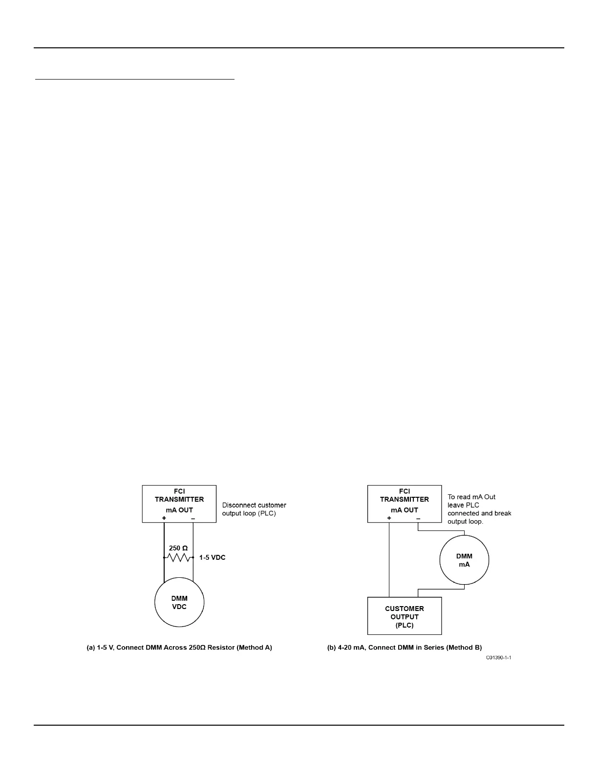
4. Connect a DMM to the transmitter 4-20 mA output by either method A or B as shown in Figure 61 below.
a. To read 1 to 5 volts, disconnect both output loop wires and connect a precision 250 Ω resistor across the output terminal. Then
connect the DMM, set to DC volts (V), across the resistor to read its voltage drop.
b. To read 4 to 20 mA current, disconnect the output loop and connect the DMM, set to milliamps (mA), in series with the output
circuit to read the current flow.
Figure 61 – DMM Hookup to Measure 4-20 mA Output
5. Turn transmitter power ON and allow the instrument 10 minutes to stabilize.
6. Verify the transmitter is in the calibration group matching the Delta R data sheet.

 Loading...


