ST80/ST80L Flow Meter INSTALLATION
Fluid Components International LLC 11
2. Mark the insertion pipe at the calculated insertion depth.
3. Ball Valve Applications Only: If a ball valve is required, install the ball valve to the process mounting coupling. Close the ball valve
to prevent the process media from leaking out when installing the packing gland with the process line pressurized.
4. Fully retract the insertion probe into the cavity of the packing gland and install the packing gland into the process mounting coupling or
ball valve as described in the previous sections: Flange Mount and NPT Pipe Thread Mount. If a ball valve is not used, make sure
to first depressurize the process line before installing.
5. Tighten the packing nut until the internal packing is tight enough to prevent excess process leakage, but also allow the insertion probe
to be inserted into place. For ball valve applications, open the ball valve after the packing nut has been tightened.
6. Align the orientation flat and flow arrow parallel to the flow direction and proceed to insert the flow element into the process media
pipe up to the insertion depth mark. For medium pressure packing gland, use the adjusting nuts on the threaded rods to pull the flow
element up to the insertion depth mark, and then tighten the adjustable nuts against the adjustable support beam to lock the insertion
probe into place. Make sure to move the adjustable nuts at the same time (equally) to prevent the probe from bending and damaging
the packing gland.
7. Tighten the packing nut another ½- to 1-turn tight (approximately 65-85 ft-lbs) until the packing has created a full seal.
8. Ensure the locking collar is properly secured to the back of the packing gland. Torque the two ¼"-28 socket head cap screws on the
locking collar to 94 in-lbs using a 3/16" hex key.
Retraction/Removal Procedure
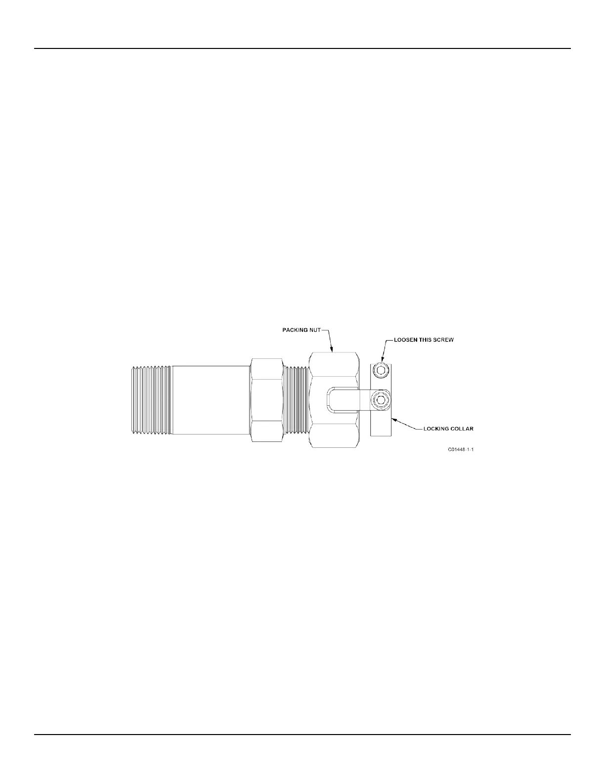
1. Loosen the socket head cap screw on the side of the locking collar. See Figure 6 below.
Figure 6 – Packing Gland Locking Collar
When using hands to restrain the retraction, be prepared for a rapid pressure impulse of the flow element. Make sure
that there are no objects directly behind the flow element as the insertion probe may retract very quickly.
2. Low Pressure (max. 50 psig [3.5 bar(g)]): Slowly loosen the packing nut until the insertion probe begins to retract. Use hands as
needed to help control the retraction. If the probe does not begin to retract itself, gently shake and pull the insertion probe until the
flow element has been fully retracted into the packing gland.
Medium Pressure (max. 500 psig [35 bar(g)]): Loosen the two nuts at the top of the adjustable support rods so that they lie slightly
above the top support beam. Slowly loosen the packing nut until the insertion probe begins to retract. The insertion probe will come to
rest when the support beam at the top of the probe makes contact with the two top adjustable nuts. Continue to slowly loosen the two
top nuts until the insertion probe has fully retracted into the body of the packing gland. If the insertion probe does not retract when
moving the two top nuts, continue loosening the packing nut until retraction resumes. Make sure to move the two top adjustable nuts
at the same time (equally) to prevent the probe from bending and damaging the packing gland. To lock the probe in a retracted state,
tighten the top and bottom adjustable nuts against the top support beam.
3. For ball valve applications: Close the ball valve immediately after retraction to seal off the process. After closing the ball valve it is
then safe to remove the flow element from the back end of the ball valve. If a ball valve is not being used, make sure to first
depressurize the process line before removing the flow element.

 Loading...


