INSTALLATION ST80/ST80L Flow Meter
10 Fluid Components International LLC
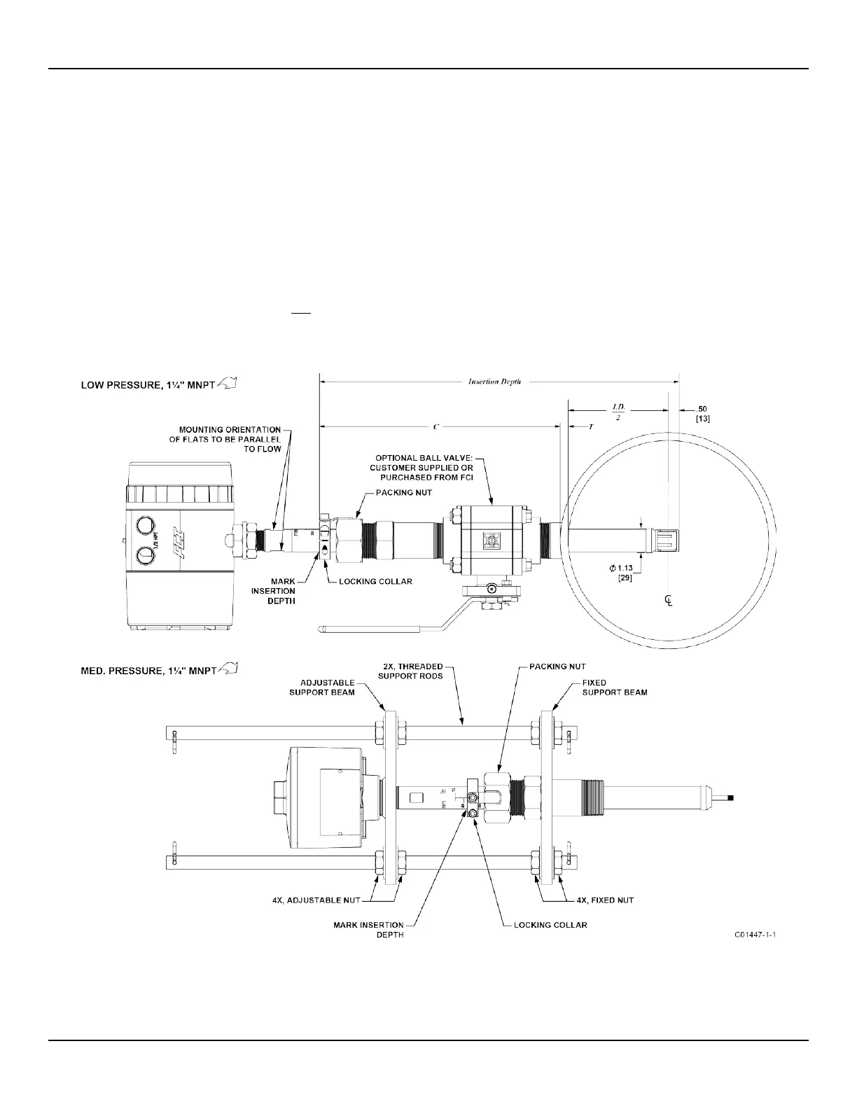
Retractable Packing Gland Mounting
A retractable low and medium pressure packing gland, with 1¼" MNPT threads or ANSI/DIN flange, and graphite or Teflon packing, is a
process connection option. FCI single point flow meters are calibrated at the centerline of the process pipe. The flow element is properly
mounted when the tip of the flow element is located .50 inches (13 mm) past the pipe centerline. Follow the below steps to install/retract
instruments with the retractable packing gland option (as applicable to your configuration, also follow the pipe thread or flange mount
procedures as described in previous sections).
1. The scale etched on the side of the insertion probe indicates the length to the tip of the flow element. Calculate the insertion depth
using the equation, variables, and Figure 5 below.
ID
= Inside Diameter of Pipe
T
= Pipe Wall Thickness
C
= Mounting Coupling with Optional Ball Valve and Installed Packing Gland Length
= .50 +
. .
2
+ +
INSERTION DEPTH = ______________
Figure 5 – Retractable Packing Gland Installation

 Loading...


