ST80/ST80L Flow Meter GENERAL
Fluid Components International LLC 3
Technical Specifications
Instrument
■ Measuring Capability
Flow rate, total flow and temperature
■ Basic Style
ST80: Insertion
ST80L: In-line (spool piece)
■ Flow Measurement Range
Insertion Style: 0.25 SFPS to 1000 SFPS [0,07 NMPS to 305 NMPS]
ST80L In-line: 0.0062 SCFM to 1850 SCFM
[0.01 NMCH to 3,140 NMCH]
– Air at standard conditions; 70 °F and 14.7 psia [21 °C and
1,01325 bar (a)]
■ Temperature Measurement Range
Up to 850 °F [454 °C] commensurate with element; see
Operating Temperature in Flow Element specification
■ Environmental Conditions
Maximum Relative Humidity: 93%
Maximum Elevation: 6561’ [2000m]
■ Media
All gases that are compatible with the flow element material
■ Accuracy
Flow:
Gas Specific Calibration: ±1.0% reading, ±0.5% full scale
Temperature:
±2 °F [±1,1 °C] (display only, flow rate must be greater than 5
SFPS [1,5 m/sec])
■ Response Time (Flow)
1 second to 63% of final value (one step change) typical with –FP
or –FPC type flow element operating in AST mode
■ Temperature Coefficient
With optional temperature compensation; valid from 10% to
100% of full scale calibration
Flow: Maximum ±0.015% of reading / °F up to 850 °F
[±0.03% of reading / °C up to 454 °C]
■ Repeatability
Flow: ± 0.5% reading
Temperature: ±1 °F [±0.6 °C] (flow rate must be greater than 5
SFPS [1,5 NMPS])
■ Turndown Ratio
Normally factory set and field adjustable from 2:1 to 100:1 within
calibrated flow range
■ Temperature Compensation
Standard: ±30 °F [±16 °C]
Optional: ±100 °F [±55 °C]
■ Agency Approvals
Class I, Division 1, Groups B, C, D
Class II, III, Division 1, Groups E, F, G
Class I, Division 2, Groups A, B, C, D
Class II, Division 2, Groups E, F, G
Type 4X, IP66/IP67, T6 Ta = -40°C to 40°C,
T5 Ta = -40°C to 55°C, T4 Ta = -40°C to 60°C
II 2 G Ex db IIC T6...T1 Gb Ta = -40°C to + 60°C
II 2 D Ex tb IIIC T85°C...T450°C Db Ta = -40°C to + 60°C
Ex db IIC T6...T1 Gb Ta = -40°C to + 60°C; IP66/67
Ex tb IIIC T85°C...T450°C Db Ta = -40°C to + 60°C; IP66/67
T6/T85°C: -40°C<Ta<+40°C, T5/T100°C: -40°C<Ta<+55°C,
T4/T135°C: -40°C<Ta<+60°C
Probe complies with Canadian Electrical code requirements
of ANSI/ISA 12.27.01-2011 as a single seal device.
■ SIL/IEC 61508: SIL 1 Compliant, SFF 71.1% to 79.1%
■ Calibration: Performed on NIST and and ISO/IEC 17025
traceable flow stands and equipment
■ Other: Follows best practices and guidelines as set forth in
ISO 14511; complies with ISO 14164
■ Storage Temperature
-76 to 150 °F [-60 to 65 °C]
Flow Element
■ Material of Construction
All-welded 316L stainless steel; Hastelloy-C optional
■ Operating Pressure
ST80 Insertion Style
Metal ferrule: 1000 psig [69 bar (g)]
Teflon ferrule: 150 psig [10 bar (g)]) (200 °F [93 °C] max.)
Packing gland (low pressure): 50 psig [3.5 bar (g)])
Packing gland (medium pressure): 500 psig [34 bar (g)])
Fixed 1" NPT: 1000 psig [69 bar (g)]
Fixed flange: per flange rating
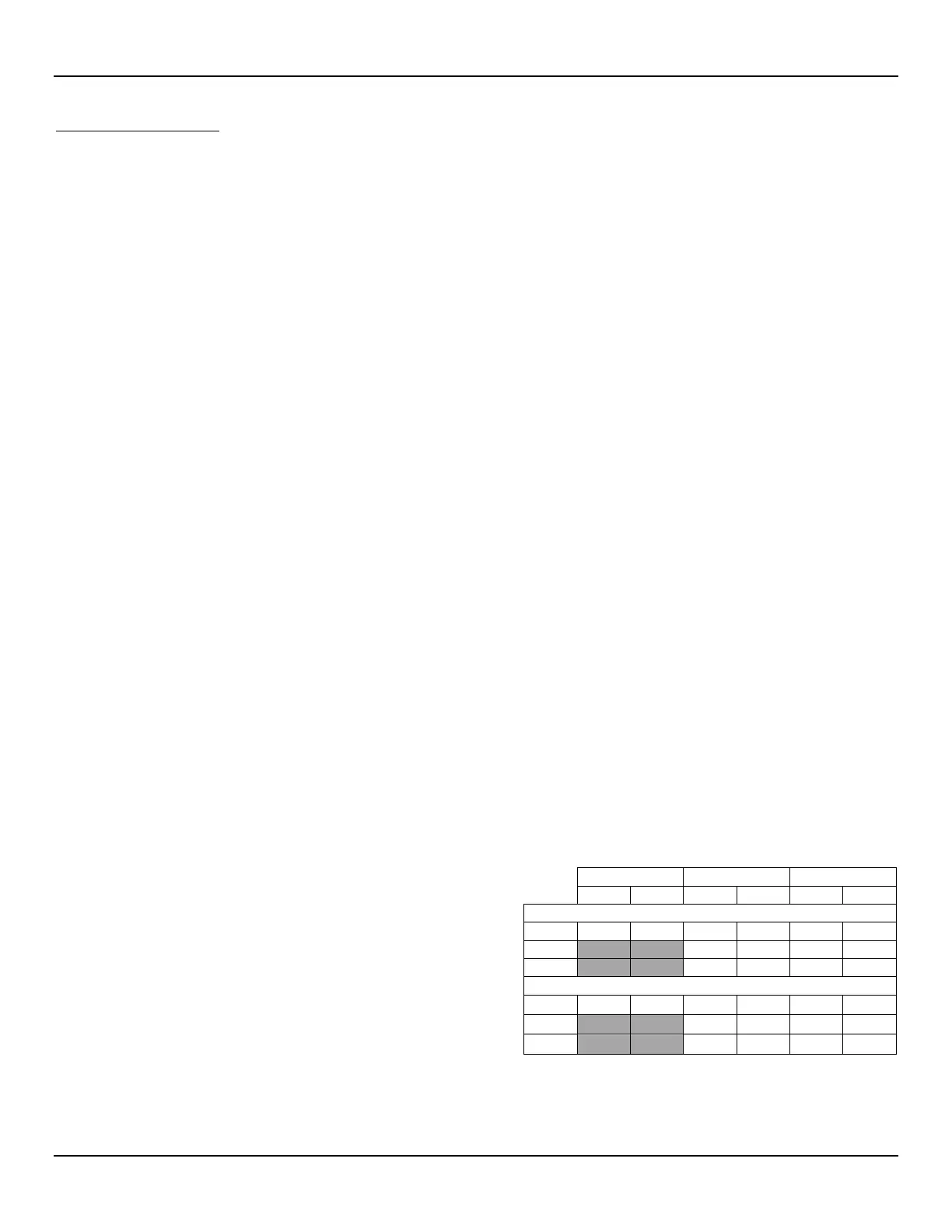
ST80L In-line Style
* 1½" and 2" Sch 80 available by special order only; contact FCI.
¾" pipe also available by special order.

 Loading...


