INSTALLATION ST80/ST80L Flow Meter
20 Fluid Components International LLC
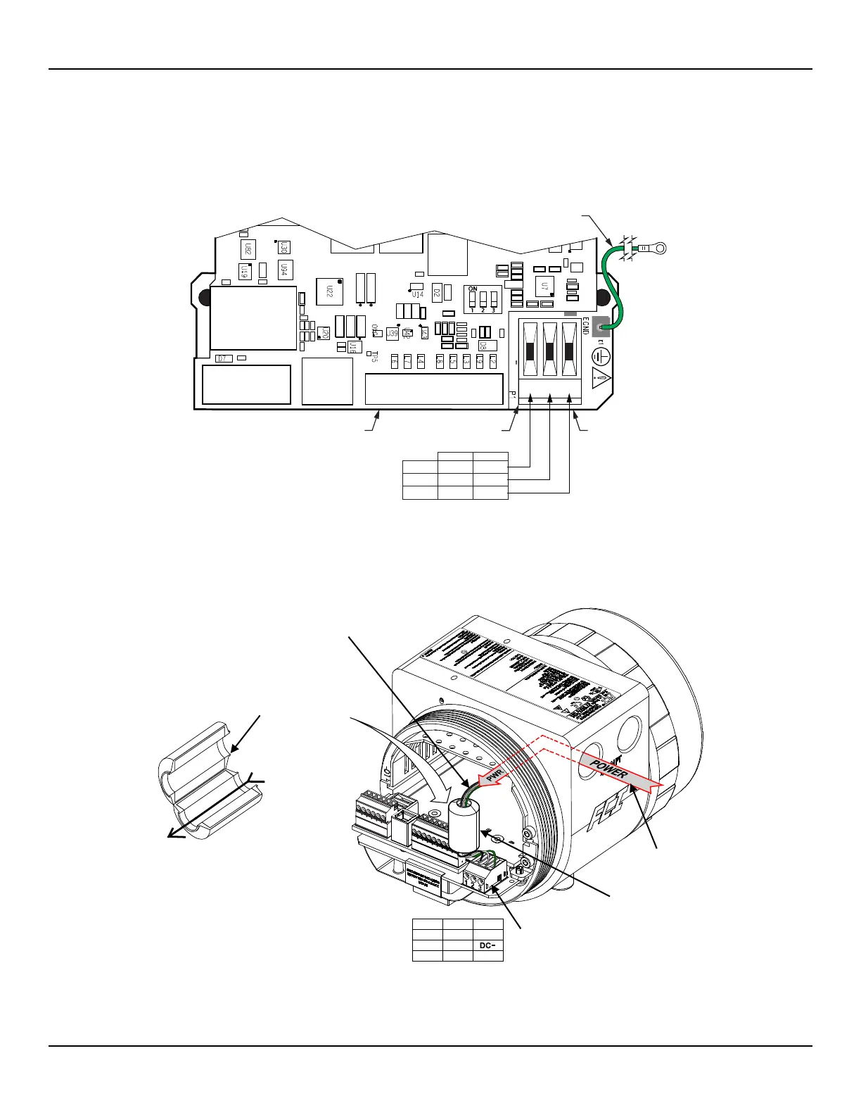
Input Power
Install an AC line disconnect switch with fuse or breaker between the power source and the flow meter.
Always disconnect power before performing maintenance on wiring.
Connect input power to the 3-position Phoenix connector P1 on the power supply board as shown in Figure 17 below. The power
connector accepts 24–12 AWG (0.2 mm
2
– 1.5 mm
2
) wire (refer to Table 2, page 17 for wire size vs. length info).
Figure 17 – Input Power Wiring
Before connecting the power wires to connector P1, install the ferrite core clamp onto the power wiring as shown in Figure 18 below. Then
insert the stripped power wire ends into the appropriate P1 connector terminals. The ferrite core clamp (supplied with the instrument as
ferrite kit FCI p/n 023638-02) protects the instrument against the adverse effects of EMI/RFI electrical noise.
Figure 18 – ST80/ST80L Ferrite Core Installation
C01412-1-1
J9
J12
J13
J10
J11
T1
J8
J25
J21
TB1
1 2 3
Term. 1
Term. 2
Term. 3
Line
AC DC
DC+
Neutral DC–
E. Gnd E. Gnd
C01446-1-2
ACTerm # DC
DC+
Line1
Neutral2
E. Gnd3 E. Gnd
(3 power leads,
straight through)
1. Strip ends of power leads.
2. Thread power leads through ferrite core (or snap open and
place wires in channel, and then snap core closed).
3. Insert power wires in appropriate P1 connector terminals.
See table/figure at right.
4. Position ferrite core as close as possible to P1 connector.
CONNECTOR, P1
(Place close to
WIRING
(AC Shown)
CONNECTOR, P1
BOARD
(Under Main Board)
(WITH RING LUG)
AC Power = 85 VAC min. to 265 VAC max.
DC Power = 19.2 VDC min. to 28.8 VDC max.

 Loading...


