ST80/ST80L Flow Meter INSTALLATION
Fluid Components International LLC 23
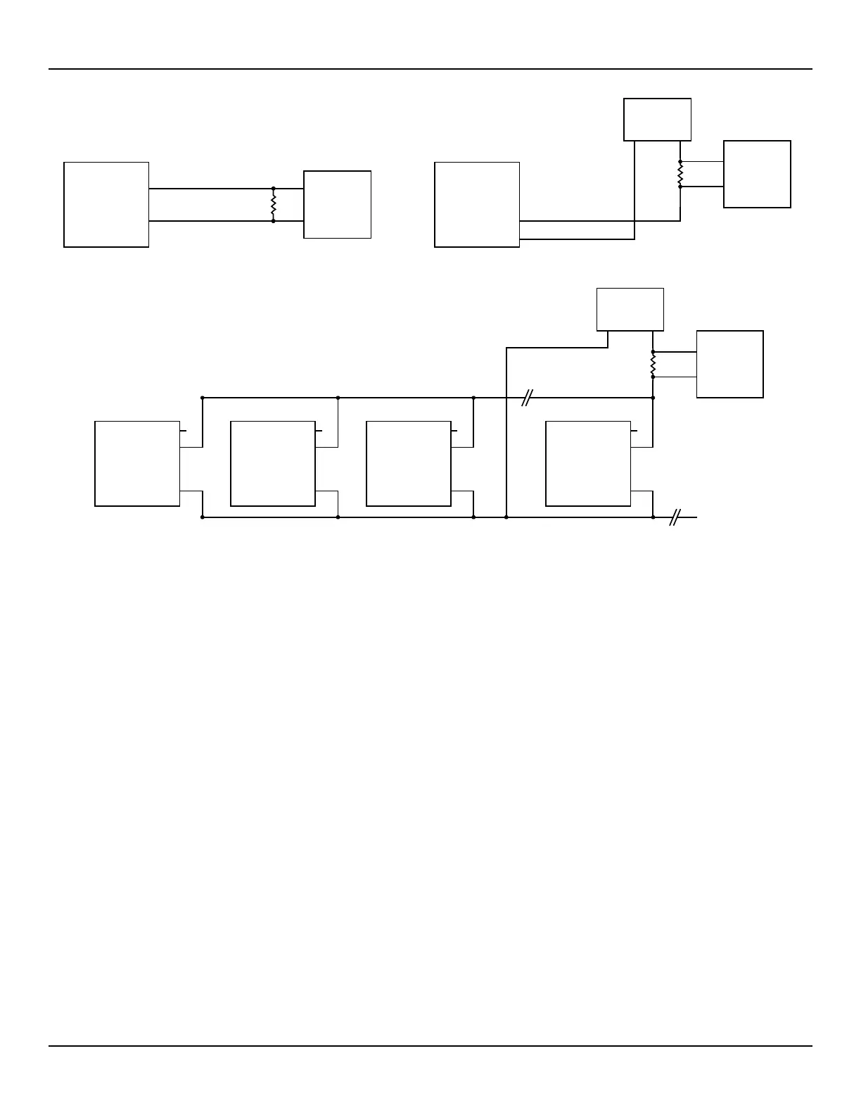
Figure 21 – Single Connection and Multidrop HART Setups
4-20 mA Output Connections
The ST80/ST80L is provided with two 4-20 mA current loop channels as standard via the J25 Phoenix connector terminals. Refer to Figure
14 and Figure 20. Similar to flow element connector TB1 the J25 connector is a detachable plug that plugs into the header socket on the
board. The connector plug accepts 28-16 AWG (0.14 mm
2
- 1.5 mm
2
) wire (refer to Table 2, page 17 for wire size vs. length info).
Ch. 1 is dedicated to HART (see above for connection details). Connect the instrument’s second 4-20 mA output (Ch. 2, J25-3) as required
for your application. Use any RTN terminal (e.g., J25-4 through J25-6) for the 2nd channel current loop return.
(b) HART Network, Multidrop
ST80/ST80L
HART
J25-1
J25-4
J25-2
ST100A
HART
J25-1
J25-4
J25-2
ST100A
HART
J25-1
J25-4
J25-2
ST100A
HART
Network P.S.
24 VDC
HART
Master
J25-1
R
LOAD
HART
I/O
J25-4
J25-2
HART+HART–
J25-4
HART
Master
R
LOAD
HART
I/O
HART
Master
R
LOAD
HART
I/O
HART+HART–
Network P.S.
24 VDC
ST80/ST80L
HART
(a) HART Single Connection
Internal Loop Power External Loop Power
+
–
–
J25-1
J25-2
ST80/ST80L
HART
NC
+
J25-1
J25-2

 Loading...


