OPERATION ST80/ST80L Flow Meter
42 Fluid Components International LLC
Analog Output Response to idR Check
During the idR sequence the analog outputs respond as listed below. Readings are taken with a 250 Ω load across Analog Output 1, 2 or 3.
NAMUR Enabled LOW
2.325 Vdc = 23.16 sfps = baseline (example: actual flow output varies from 1-5 volts)
0.900 Vdc = idR In Progress
1.000 Vdc = momentary state
2.326 Vdc = after 3 seconds. idR values are displayed now.
NAMUR Enabled HIGH
2.325 Vdc = 23.16 sfps = baseline (example: actual flow output varies from 1-5 volts)
5.250 Vdc = idR In Progress
1.000 Vdc = momentary state
2.326 Vdc = after 3 seconds. idR values are displayed now.
NAMUR Enabled Disabled
2.325 Vdc = 23.16 sfps = baseline (example: actual flow output varies from 1-5 volts)
1.000 Vdc = idR In Progress
2.326 Vdc = after 3 seconds. idR values are displayed now.
Using Digital Outputs
Digital busses (includes HART, Modbus, and FOUNDATION Fieldbus/PROFIBUS) are mutually exclusive, meaning only one can be active at
a time. When a particular digital output is specified at order time the unit is configured appropriately at the factory. Use the ST80/ST80L
configuration software (Configuration/Output) to change the digital output selection. Refer to the ST80/ST80L Configuration Software
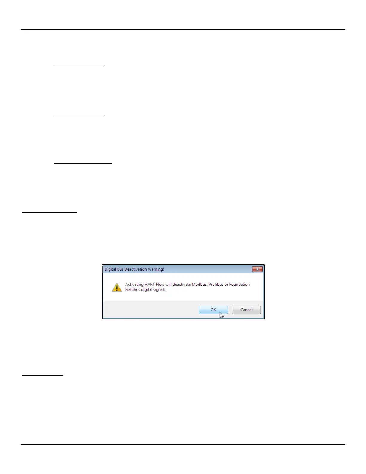
manual 06EN003491 for details. Note that enabling a digital bus will deactivate the other digital bus currently in effect. Figure 46 below
shows the configuration software dialog box that appears when the user assigns 4-20 mA #1 to HART Flow with another digital bus
already active.
Figure 46 – Digital Bus Deactivation Warning When Enabling HART
FOUNDATION Fieldbus/PROFIBUS operation requires the optional Fieldbus/PROFIBUS add-on card installed on the main board. Refer to
the F
OUNDATION Fieldbus manual (06EN003492) and PROFIBUS manual (06EN003493) for operation details on these digital outputs.
HART Operation
HART (Highway Addressable Remote Transducer) is a communication protocol that superimposes a low level digital data signal on a 4-20 mA
current loop. The primary function of the instrument’s HART interface is to present process data via process data commands 1, 3 and 9. Use the
configuration software (Configuration/Output) to set the instrument to HART mode by assigning 4-20 mA #1 to HART FLOW. Refer to the
ST80/ST80L Configuration Software manual 06EN003491 for details.
The ST80/ST80L does not implement the HART Burst mode. A HART master that supports HART 7.0 and higher is required. If using a
HART communicator, a unit that supports HART 7.0 or higher is required (i.e. Emerson 475 Communicator). Connect the installation
(factory/plant) HART wiring to the instrument as described in HART Connections, page 22.

 Loading...


