ST80/ST80L Flow Meter INSTALLATION
Fluid Components International LLC 19
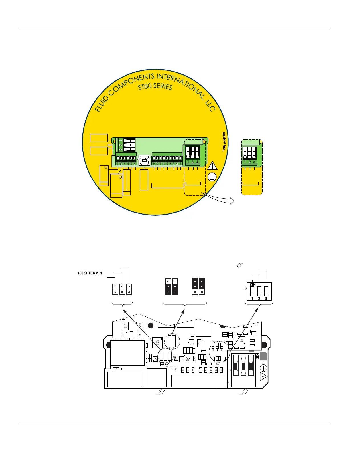
Electronics Enclosure Label
Affixed to the inside of the blind lid is a label that identifies the ST80/ST80L’s jacks and connectors (with terminal assignment). See Figure
15 below. Use this label as a guide when wiring the instrument. Note that the PCB silkscreen also provides connector identification.
Figure 15 – ST80/ST80L Electronics Enclosure Label
Configuration Jumpers/DIP Switch
When wiring the instrument for Modbus/Fieldbus/PROFIBUS make sure that the instrument is properly configured as shown in Figure 16
below. Refer to Modbus Connections on page 24 and Foundation Fieldbus/PROFIBUS Connections (Option) on page 25 for details.
Figure 16 – Bus Configuration 2 mm Jumper Headers and DIP Switch
J21
4-20mA RTN
4-20mA
INT HART RTN
EXT HART +
INT HART +
CH1
CH1
B (+)
J8
J25
TB1
P1
FIELDBUS_A
PROFIBUS/FIELDBUS
FIELDBUS_B
A (–)
RETURN
85-265 V
A.C.
EXT HART RTN
4-20mA
4-20 mA RTN
RETURN
AC LINE
AC NEUT
E.GRND
SIGNAL INPUT
SENSOR.1
PC CONFIG
USB
SHIELD
REF SEN
REF EXC
GND
GND SEN
ACT SEN
ACT EXC
HTR RTN
HTR EXC #1
P1
19.2-28.8 V
D.C.
DC +
DC -
E.GRND
CH2
C01428-1-1
C01419-1-1
J9
J12
J13
J10
J11
T1
J8
J25
J21
TB1
J11
J10
J9
J12
J13
J12
J13
MAIN BOARD
MODBUS FF/PROFIBUS
LINE PULLDOWN
LINE PULLUP
#SIM_ENABLE
#NV_ERASE
#HW_LOCK
ATION
POWER SUPP LY BOARD
(Under Main Board)
1
2
3
1
2
3
1
2
3
ON POSITION
ACTIVE WHEN ON
LINE CONFIG. BUS SELECT, J8 FF/PROFIBUSADD-ON CARD
DIAG/TEST
1
2
3
DC Version
Power Labeling

 Loading...


