IN CASE OF EMERGENCY
248
302 F1A0174
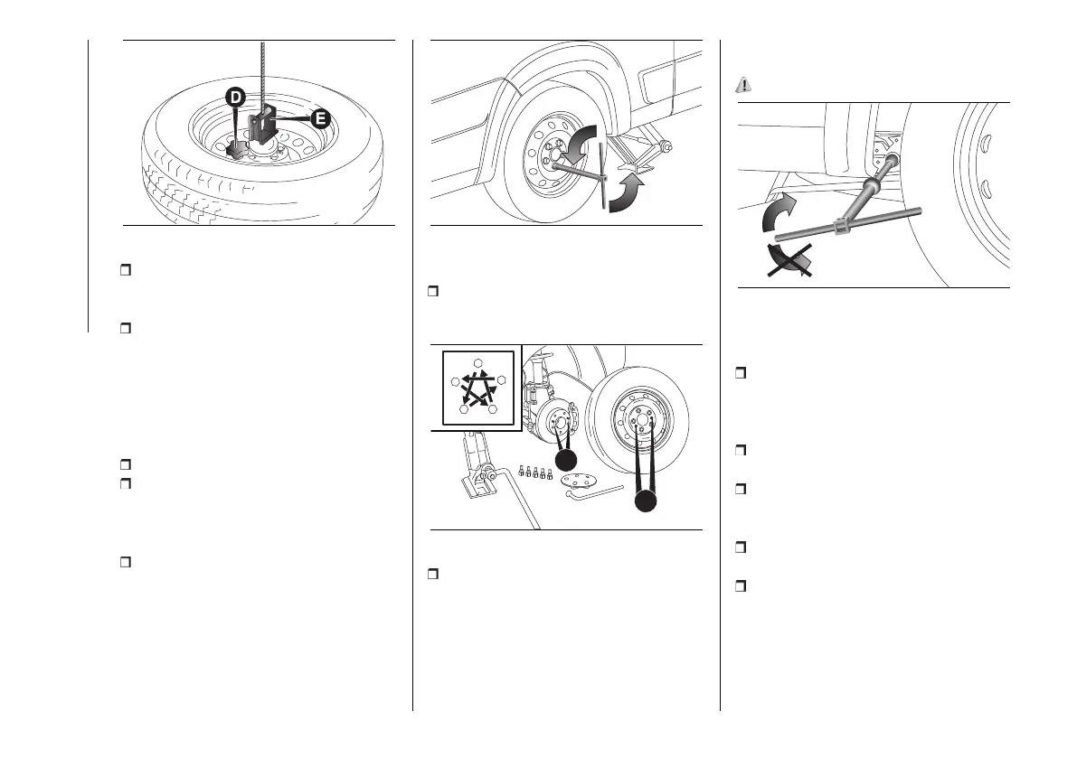
with the tools assembled, undo the
bolts fig. 303 fully and remove the
wheel;
fit the spare wheel, lining up
the holes (G) fig. 304 with the
corresponding pins H. While fitting
the spare wheel, make sure that the
mating surfaces are clean and free of
impurities that could later cause the
fixing bolts to come loose;
screw in the 5 fastening bolts;
assemble the tools to tighten the
bolts fully, passing alternately from one
bolt to the diagonally opposite one,
following the scheme shown in fig. 304;
use the wheel removal wrench to
lower the vehicle and remove the jack.
303 F1A0422
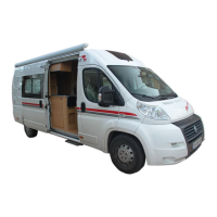
At the end of the operation:
take the replaced wheel, reattach it
to the support (E) fig. 302 and tighten
the knob (D);
304 F1A0176
introduce the assembly tool fig. 301
provided with the suitable extension
(B) fig. 300 on the screw (A) fig. 300 of
the spare wheel housing manoeuvring
device and turn clockwise to lift the
spare wheel back up until it is fully
supported in its housing beneath the
floor pan (D) fig. 301.
202)
305 F1A0430
For vehicles with alloy rims, proceed as
follows:
carry out the above described
operations for changing the wheel until
loading the punctured wheel on the
spare wheel lifting device;
take the kit from the tool bag, located
in the glove compartment;
the kit includes one bracket, three
special screws and one Allen spanner,
10 size;
go to the rear side of the vehicle
where the spare wheel is located;
make sure that all of the cable for
the spare wheel lifting device has been
unrolled, grip the bell and position it
inside the circular bracket fig. 306;