Notification Appliance/Auxiliary Power Circuits Control Panel Installation
FCP-300/FCP-300ECS Manual — P/N LS10145-002FK-E:A 3/12/2021 47
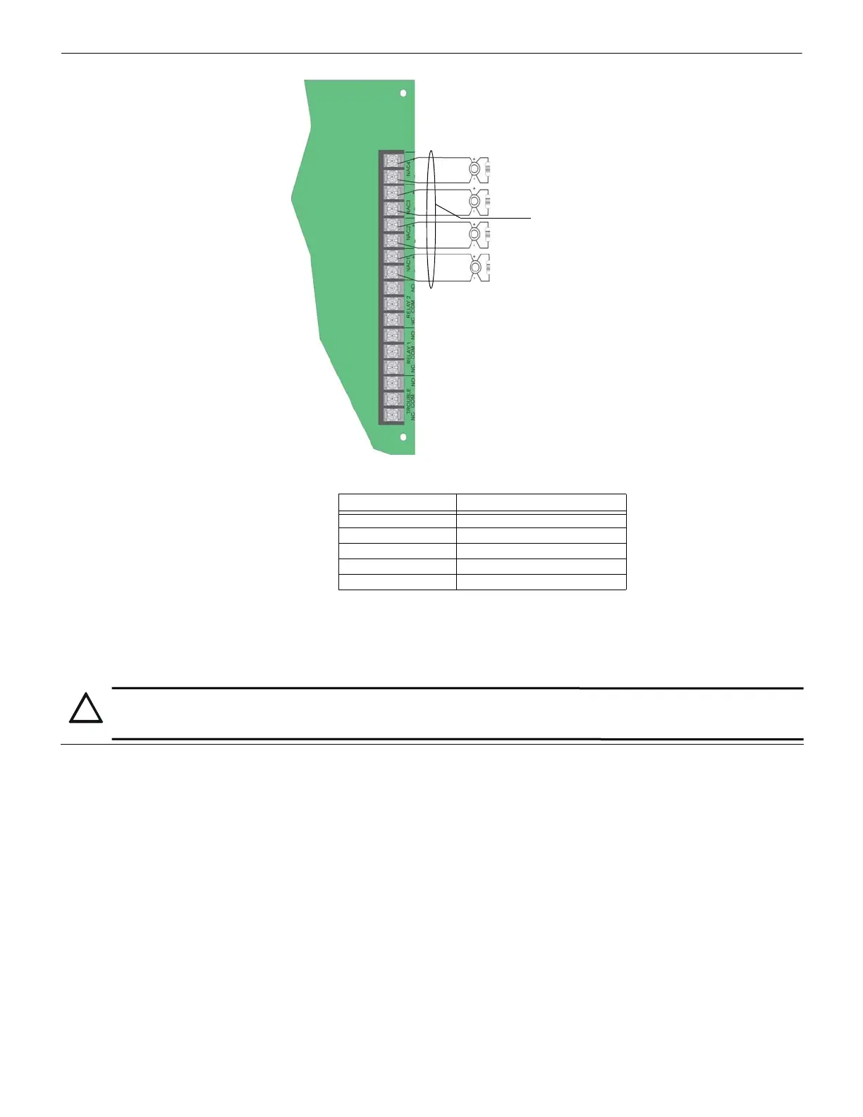
Figure 4.41 Class B Notification Appliance Circuit Wiring
The maximum voltage drop is 3V per Class A circuit. See Table 4.5.
Class A Notification Wiring
You must use an appliance from the list of compatible appliances in Appendix A.
To install a Class A notification appliance circuit, do the following.
1. Wire the Class A notification appliances as shown in Figure 4.42.
Current Maximum Impedance
1.0A 3Ω
1.5A 2Ω
2.0A 1.5Ω
2.5A 1.2Ω
3.0A 1.0Ω
Table 4.5 Maximum Impedance Class A
Alarm Polarity
4.7 kΩ EOL
Supervised
Power-Limited
Notification Wiring
Max. Impedance:
All Circuits are Synchronized
(Regulated). Rated at 27.4 VDC @ 3A
Max.
CAUTION:
For proper System supervision, do not use the looped wire under the terminals marked + and – of the Flexput connectors. The Break wire
runs to provide supervision of connections.