FIMER_PVS-175-TL A.1 Version_Product manual_EN_RevC-
F
39
Overvoltage surge arrester monitoring
The inverter monitors the status of the overvoltage surge arresters (21) (25) and generates a warning
in the event of a fault (viewable via monitoring system, web user interface or FIMER Installer for Solar
Inverters APP).
Data transmission and control
Embedded multi communication interfaces (WLAN, Ethernet, RS485) combined with a Sunspec
compliant Modbus protocol (RTU/TCP) allow the inverter to be easily integrated with any third party
monitoring and control systems that support the same Sunspec standard.
NOTE – D The Modbus RTU/TCP register map is the same for all communication interfaces
(Ethernet, RS-485 and Wireless communication) of the inverter.
NOTE – D Please contact the FIMER technical support or get access to Sunspec alliance
website for further information on Modbus Sunspec products.
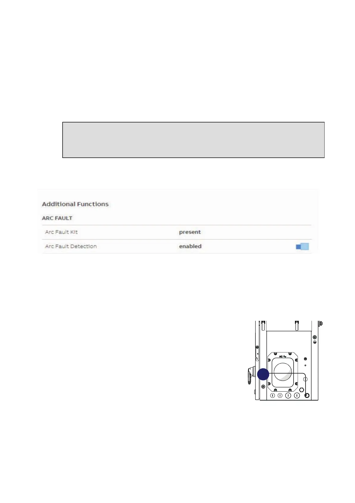
DC Series Arc Fault Circuit Interrupter
DC Series Arc Fault Circuit Interrupter function is provided as an additional function only for dedicated
inverter models.
Arc fault reset button
The red “GFI” LED indicates that the inverter has detected an arc fault in the DC side photovoltaic
array.
If an arc fault occurs (red “GFI” LED turned on) the inverter immediately disconnects from the grid. Is
possible to reset the alarm pushing the button on the left side of DC wiring box (57).
• If the inverter reconnects normally to the grid, the fault was due to
temporary or intermittent conditions.
If this malfunction occurs, have the PV plant inspected by a
specialist. Arc faults are more likely in damp conditions, and signal
an insulation breakdown.
• If the inverter does not reconnect to the grid, lock out/tag out both
the AC and DC disconnects, inspect the PV modules to identify the
root cause and repair the fault.
Arc fault detection
The Arc Fault Circuit Protection required by NFPA 70 Article 690.11 is provided by the inverter.
The AFD performs a self-test when the system is started:
• If the self-test results are OK, the inverter will continue to AC grid connection.
• If a potential problem on the AFD board is detected, the self test will result in error E053.
During normal operation the input current is continually measured and analyzed. If a DC arc fault is
detected during operation, the inverter disconnects from AC grid and generates an E050 error code
(readable through internal Webserver).
57