FIMER_PVS-175-TL A.1 Version_Product manual_EN_RevC-
F
21
Models and range of equipment
NOTE – D The choice of the inverter model must be made by a qualified technician who
knows about the installation conditions, the devices that will be installed in addition to the
inverter and possible integration with an existing system.
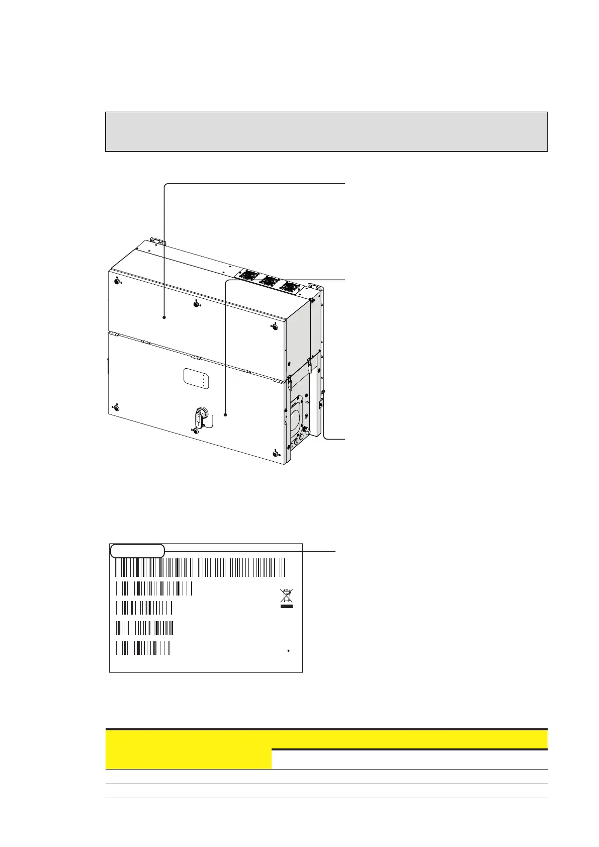
The parts of equipment which make up the inverter are:
Three-phase power module:
• PVS-175-TL-POWER-MODULE-1
175kW output power with precharge module
• PVS-175-TL-POWER-MODULE-2
175kW output power without precharge module
Wiring box:
• WB-SX-PVS-175-TL.
24 quick fit connector pairs
(2 each mppt)
DC disconnection switches
SPD Type 2 (DC & AC)
• WB-SX2-PVS-175-TL.
24 quick fit connector pairs (2 each mppt)
DC disconnection switches
AC disconnection switch
SPD Type 2 (DC & AC)
Mounting Braket:
• PVS-175-TL-BRACKET.
Refer to the identification labels present on the Power Module and Wiring Box, in order to identify the
presence of below mentioned Kit:
• Arc Fault circuit interrupter
• Anti-PID
MODEL NAME reports the model number
and some additional information.
Example:
WB-SX2-PVS-175-TL;A1;24IN;AFCI
The AFCI suffix indicates that the “
Arc Fault
circuit interrupter” is pre-installed on the
inverter
.
Verify the prensence of the correspondent Acronym in the complete string to identify if the specific kit
is pre-installed in Power Module and/or in the wiring Box according to the below table:
KIT
Acronym
Wiring Box Power Module
Arc Fault AFCI AFCI
Anti PID Anti-PID
MODEL NAME
POWER-ONE ITALY S.p.A
Via S.Giorgio 642, Terranuova Bracciolini (AR), 52028, Italia
P/N:PPPPPPPPPPP
WO:XXXXXXX
SO:SXXXXXXXX Q1
SN:YYWWSSSSSS WK:WWYY