FIMER_PVS-175-TL A.1 Version_Product manual_EN_RevC-
F
154
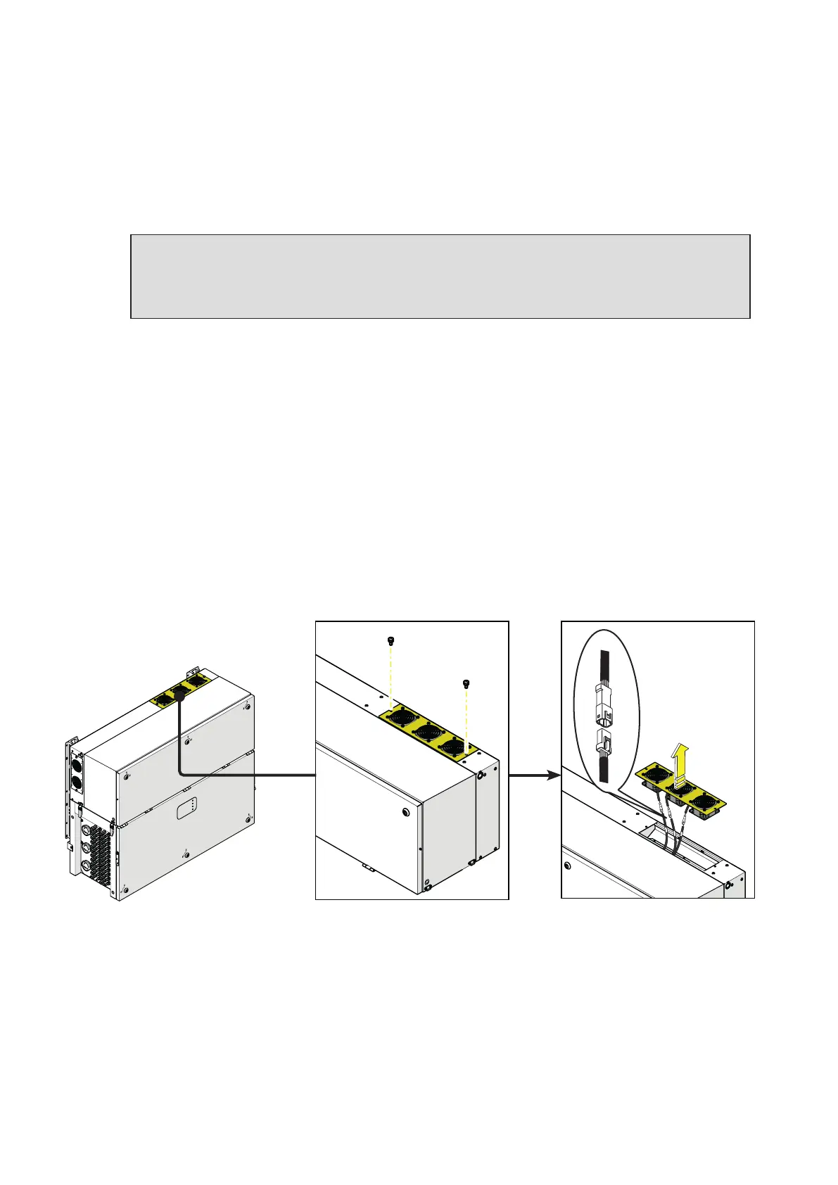
Replacing of the top fan section
Procedure for replacing the top fan sections:
• Open the DC disconnect switches (19).
• Open any AC disconnect switch downstream of the inverter or the AC disconnect switch (09) (only
on -S2, -SX2 model).
WARNING – B Do not open the front wiring box cover (07) or the front power module cover
(06).
WARNING – B Wait the internal capacitors to be discharged (the discharge time of the stored
energy is indicated on the regulatory label), and check that fans are completely stopped.
• Remove the 2 screws located on fan section.
• Tilt the fan section as shown in the picture.
• Pull out the fan section.
• Disconnect the 2 fan connectors.
•
Take the new fan section and connect the 2 fan connectors. During this phase pay attenction to
connect the fan to the correspondent cable; on each fan cable coming from the power module are
applied labels that indicates the fans number (from FAN1 to FAN5).
• Place the new fan section following the previous steps in reverse way.
• Screw the 2 fastening screws previosly removed.
PVS