FIMER_PVS-175-TL A.1 Version_Product manual_EN_RevC-
F
71
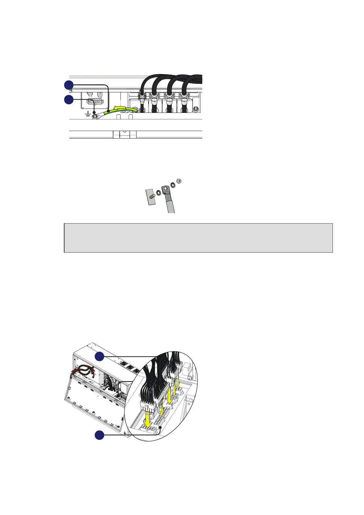
• Install the protective earth cable lug (31) to the protection earth connection point (36) situated on
the internal bottom side of power module.
36
31
Use the washers and bolt supplied in the power module installation kit:
1 = toothed washer
2 = cable lug
3 = toothed washer
4 = M5 nut
1
2
3
ATTENTION – A The cable lug must be installed with a tightening torque of 3Nm (2.2 ft-lb).
ATTENTION – A Any failure of the inverter when it is not connected to earth through the
appropriate connection point is not covered by the warranty.
Connection of the interface signal connectors
The interface signal connectors (male) (35) are situated into right side of power module and they are
composed by 8 connectors.
•
Connect all the interface signal connectors (35) with the related interface signal connectors (female)
(32) (push the connector until you hear a locking “click”).
All connectors have a different pin-out in order to avoid any connection error.
32
35