FIMER_PVS-175-TL A.1 Version_Product manual_EN_RevC-
F
153
Replacing of fan sections
WARNING – B The following operation must be carried out wearing the appropriate insulating
composite gloves class 0 EN60903 (1000Vac-1500Vdc) resistant to electric arc class 2
(7kA) EN61482-1-2 in combination with protective overglove in leather EN420 – EN388.
NOTE – D When replacing the external fan sections it’s strictly recommended to clean the
fins of internal heatsink using compressed air (blowing air from top and the side to the rear
of the inverter).
Replacing of the side fan section
Procedure for replacing the side fan sections:
• Open the DC disconnect switches (19).
• Open any AC disconnect switch downstream of the inverter or the AC disconnect switch (09) (only
on -S2, -SX2 models).
WARNING – B Do not open the front wiring box cover (07) or the front power module cover
(06).
WARNING – B Wait the internal capacitors to be discharged (the discharge time of the stored
energy is indicated on the regulatory label), and check that fans are completely stopped.
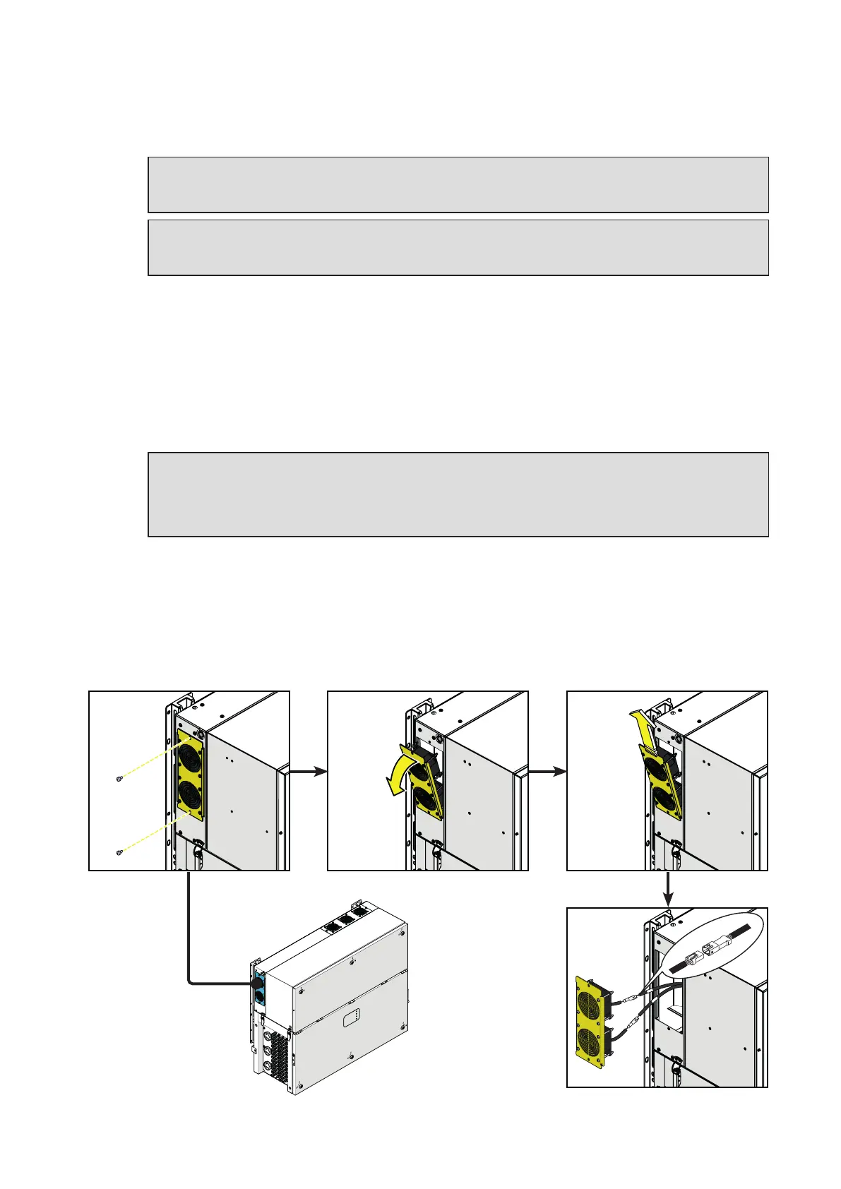
• Remove the 2 screws located on fan section.
• Tilt the fan section as shown in the picture.
• Pull out the fan section.
• Disconnect the 2 fan connectors.
•
Take the new fan section and connect the 2 fan connectors. During this phase pay attenction to
connect the fan to the correspondent cable; on each fan cable coming from the power module are
applied labels that indicates the fans number (from FAN1 to FAN5).
• Place the new fan section following the previous steps in reverse way.
• Screw the 2 fastening screws previosly removed.
PVS