FIMER_PVS-175-TL A.1 Version_Product manual_EN_RevC-
F
57
15
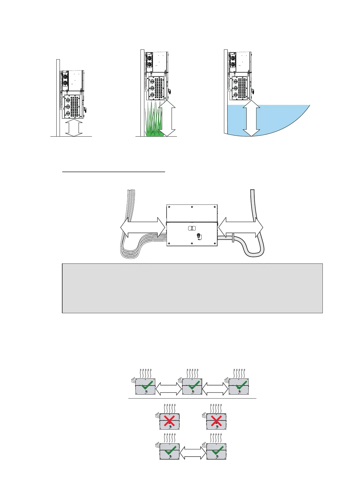
cm
50
cm
50
cm
3. Cables bending radius.
Sides (C) minimum required free space may depends from cable type (cable dimension, bending
radius, etc..). This evaluation must be done by the installer during the plant design phase (refer to
“Routing the cables to the inverter” paragraph for more information). In any case the minimum
required free space useful for a proper ventilation of the unit (near side fans) cannot be under 15 cm
on the right side and 30cm on the left side.
PVS
C C
NOTE – D In case of manual installation, using handles (04), consider a free side space to lift
the inverter of 60 cm minimum.
NOTE – D In case of installation with lifting equipments (eyebolts and ropes) the side
distances (C) could be reduced at the minimum required but a subsequent manual lifting it
will no longer be possible: in this case the lifting equipments should remain available on the
field for any subsequent operation.
Installation of multiple units
• In case of installation of multiple units in the same place, position the inverter side by side paying
attention to keep the minimum clearance distances (measured from the outer edge of units) as
shown in the picture below.
50 cm
20”
50 cm
20”
50 cm
20”
• The installation of two inverters positioned back to back is also permitted on a structure which must