FIMER_PVS-175-TL A.1 Version_Product manual_EN_RevC-
F
43
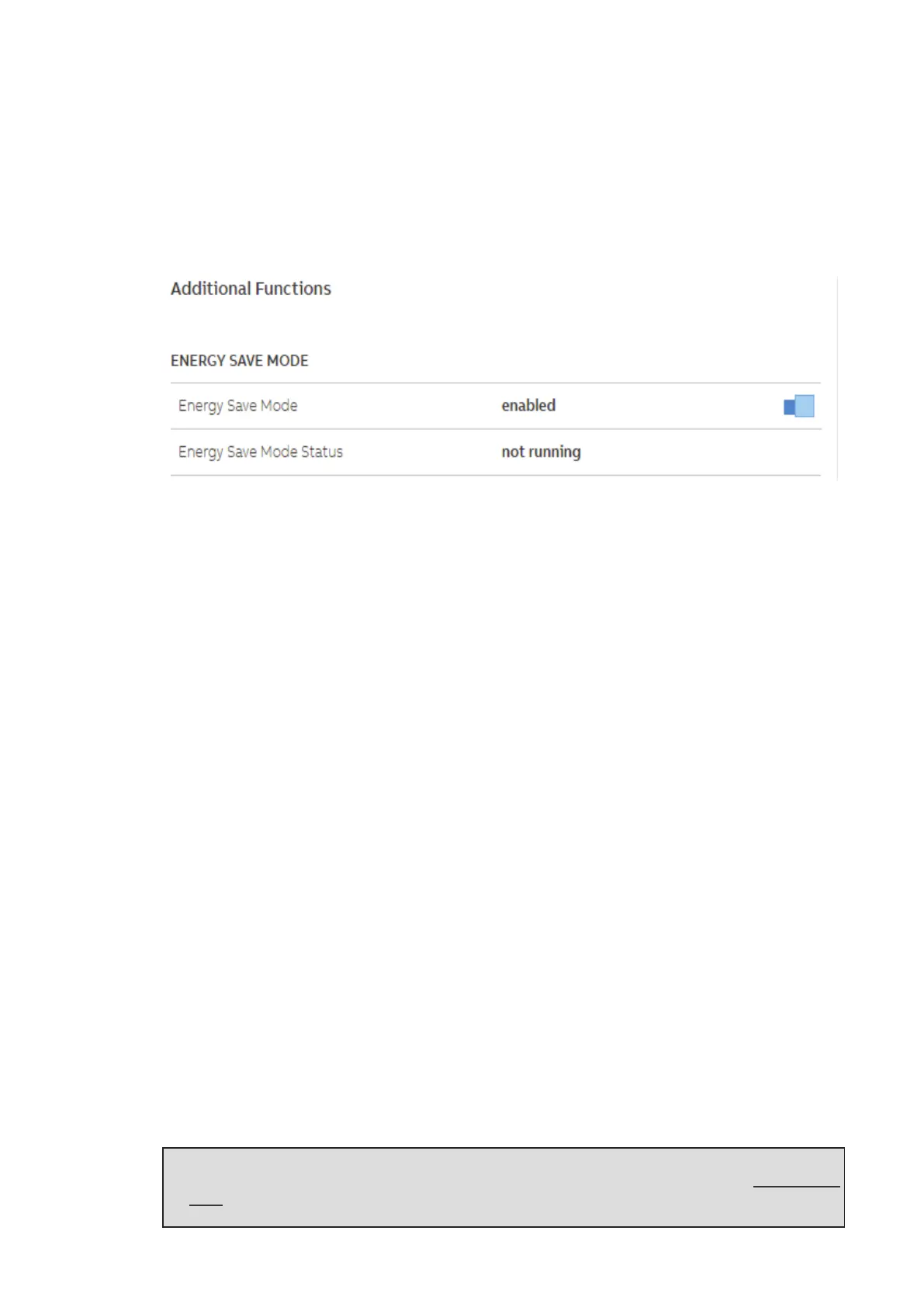
This is a Mode that minimizes the power consumption of the inverter during the night.
It is possible to enable or disable Energy Save Mode through Web UI. Anyhow, when other functions
like “Nightmode” or “Anti-PID” are enabled, inverter will not enter the Energy Save Mode.
Inverter can operate in this mode when there are no other requests during the night and inverter
minimizes the power consumption. For any other requests that arrive, inverter is able to wake up from
the energy save mode and enter Nightmode, Anti-PID, FW upgrade or other desired functionalities.
Following sections show how to manage this feature through Web UI and typical use cases.
Communication interfaces
The integrated ethernet and wireless board allows the local or remote connection to the inverter.
The inverter provide the following integrated communication interfaces:
• Wireless channel (IEEE 802.11 b/g/n@2.4GHz)
The use of wireless channel is recommended to access to the integrated Web User Interface by
using any WLAN standard device (PC, tablet. smartphone) for commissioning and setting
parameters. Additionally a second radio channel is available and can be used for connection to a
wireless router.
• 2x Ethernet ports (44) (45) (10/100BaseTx - RJ45 plugs)
The ports are configured by default for enabling daisy chain connection of the inverters over the
Ethernet bus.
In order to improve the reliability of the communication with the inverters it is also allowed to create
ring shape layout by using this Ethernet bus.
• 1x RS485 ports (43) (terminal block)
The port enables daisy chain connection of the inverters over the serial line (slave mode). The port
can either be used for connecting supported accessories (like weather station, meter...): in this case
data from accessories will be logged and transferred to the cloud by inverter itself (master mode).
Ethernet bus connection
By default the two Ethernet ports (44) (45) of the inverters are already configured for enabling
communication over daisy chain layout.
Once the inverter is physically connected does not need specific settings: after the first turning on,
the inverter automatically got all needed network parameters with or without the presence of a DHCP
server.
If an internet connection is available on site, the inverters will be automatically configured to transmit
telemetry data to Aurora Vision Cloud without the need of installing any additional device (logging
capability are already integrated into the inverter by default).
NOTE – D Aurora Vision Plant Management platform is the FIMER cloud solution allowing
customer to remotely monitor and manage its own solar plants. Please refer to www.fimer.
com or contact FIMER technical support for further information on how getting an Aurora
Vision account.