FIMER_PVS-175-TL A.1 Version_Product manual_EN_RevC-
F
22
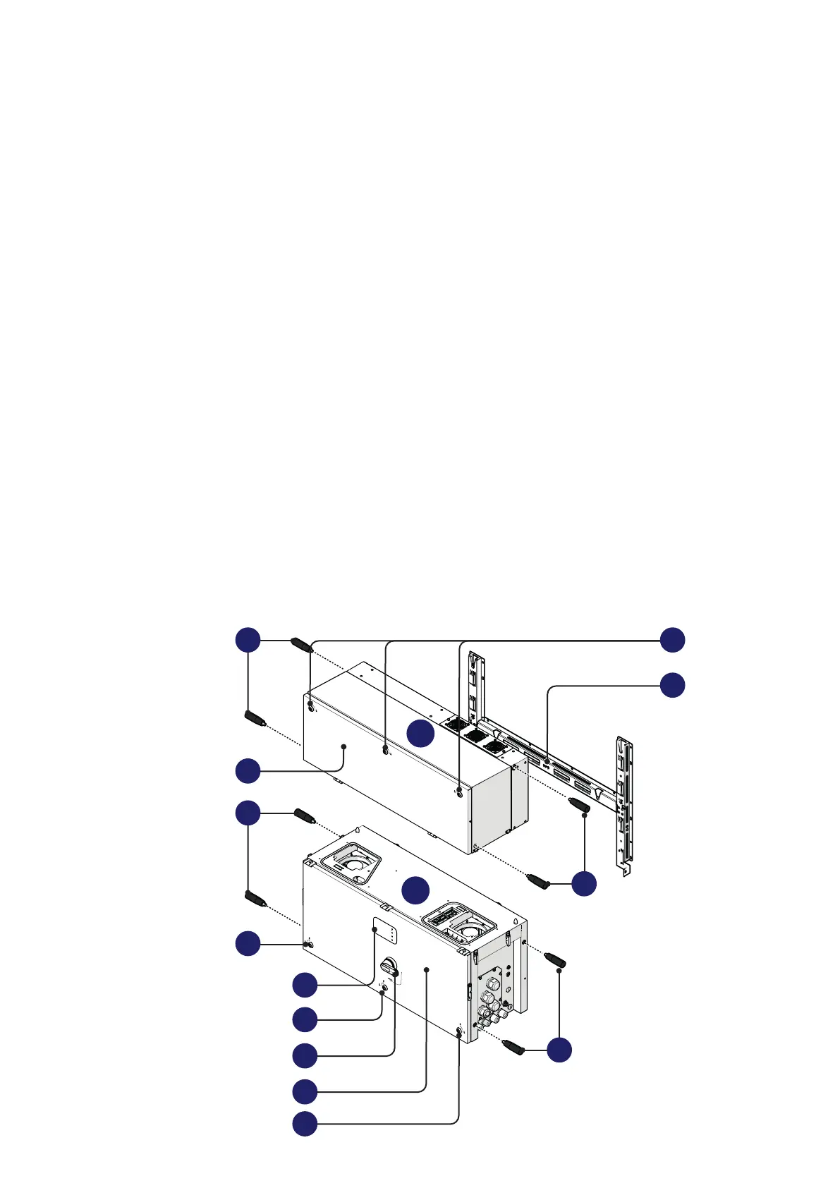
Component reference numbers
01 Power module
02 Wiring box
03 Mounting bracket
04 Handles
05 Cover quarter cam locks
06 Power module front cover
07 Wiring box front cover
08 LEDs panel
09 AC disconnect switch (-SX2)
10 Protective earth point (ext.)
11 Phases cable glands
12 Protective earth cable gland
13 Signal cable glands
14 RS485 Service connector
15 Cover support brackets
16 Side latches
17 Rear pins for bracket assembly
18 DC input quick fit connectors
19 DC disconnect switches
20 Junction screws
21 DC surge arrester plate
22 DC cable duct
23 AC protective shield
24 DC overvoltage surge arresters
25 AC overvoltage surge arresters
26 Communication and control board
27 AC connection busbar
28 Protective earth point (int.)
29 DC interface faston connectors
30 Opening for DC interface cables
31 AC interface cable lugs
32 Interface signal connectors (female)
33 DC interface cables
34 AC interface connection point
35 Interface signal connectors (male)
36 Interface protective earth point
37 FIMER RS485 service Ethernet connector
(RJ45) (service only)
38 RS485 FIMER service 120Ohm termination
res. (service only)
39 DRM0 activation switch
40 RS485 line 120Ohm termination res.
41 Alarm terminal block
42 Remote ON/OFF terminal block
43 RS485 line terminal block
44 Ethernet connector 2 (RJ45)
45 Ethernet connector 1 (RJ45)
46 USB connector
47 CR2032 Backup battery
57 AFD reset button (only when the DC Series
Arc Fault Circuit Interrupter kit is installed)
PVS-175-TL - External view
PVS
03
01
02
06
05
08
09
07
05
04
05
04 05
04
04