FIMER_PVS-175-TL A.1 Version_Product manual_EN_RevC-
F
161
Procedure for dismantling the equipment
WARNING – B The dismantling operations must be carried out with the equipment
disconnected from any voltage sources. Refer to “Inverter total de-energization and safe
access” paragraph on this manual to know all the necessary step to safely operate on the
inverter.
ATTENTION – A Never open the power module (01) or wiring box (02) in the case of rain,
snow or a level of humidity >95%. Always carefully seal all unused openings.
Even though the device is equipped with an anti-condensation valve, air with extremely high levels of
humidity can lead to the creation of condensation inside the inverter.
As the inverter is almost completely insulated from the outside, condensation can also form after
maintenance interventions in certain weather conditions.
ATTENTION – A During dismantling always protect the inverter parts that are installed and
exposed to the weather elements!
ATTENTION – A Staff authorised to carry out the dismantling operations must be specialised
and experienced in this job. They must also have received suitable training on equipment
of this type.
The inverter consists of an power module (01), a wiring box (02) and a mounting bracket (03) which
may be dismantled separately.
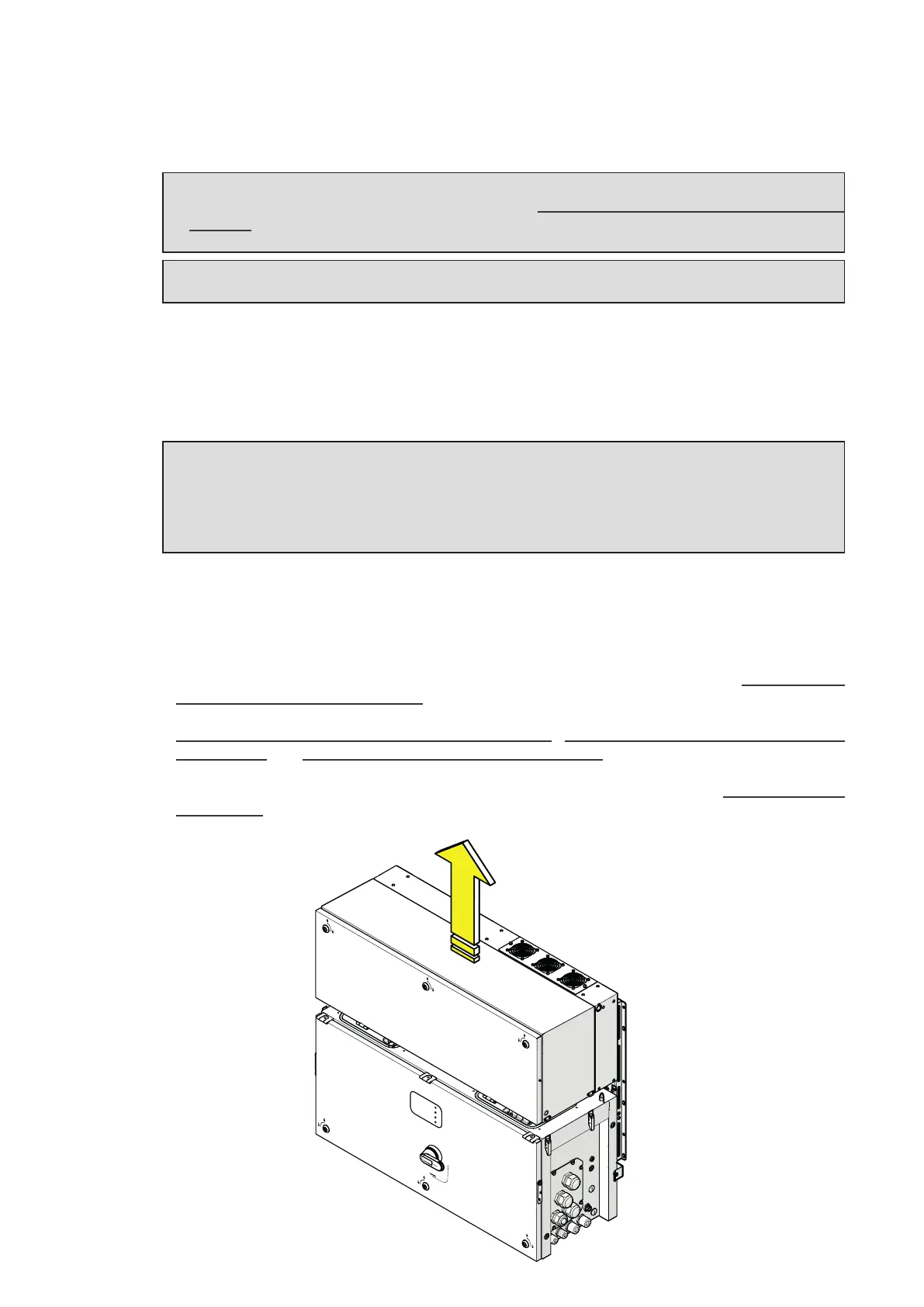
To dismantling and disassemble the power module (01) follow these steps:
• Disconnect any external voltage sources and isolate the equiment referring to the “Inverter total
de-energization and safe access” paragraph.
•
Disconnect all internal connectors between power module (01) and wiring box (02) reffering to
“Connection of the AC interface power cables”, “Connection of the interface signal
connectors” and “Connection of the DC interface cables” paragraphs (Follow the indications
for connection procedure but in the reverse order).
•
Disjoint the power module (01) and wiring box (02) enclosures reffering to “Final fastening
operations” paragraph (Follow the indications for the mounting procedure but in the reverse order).
• Slightly lift the power module (01) to allow the gasket protective covers insertion.
PVS