FIMER_PVS-175-TL A.1 Version_Product manual_EN_RevC-
F
162
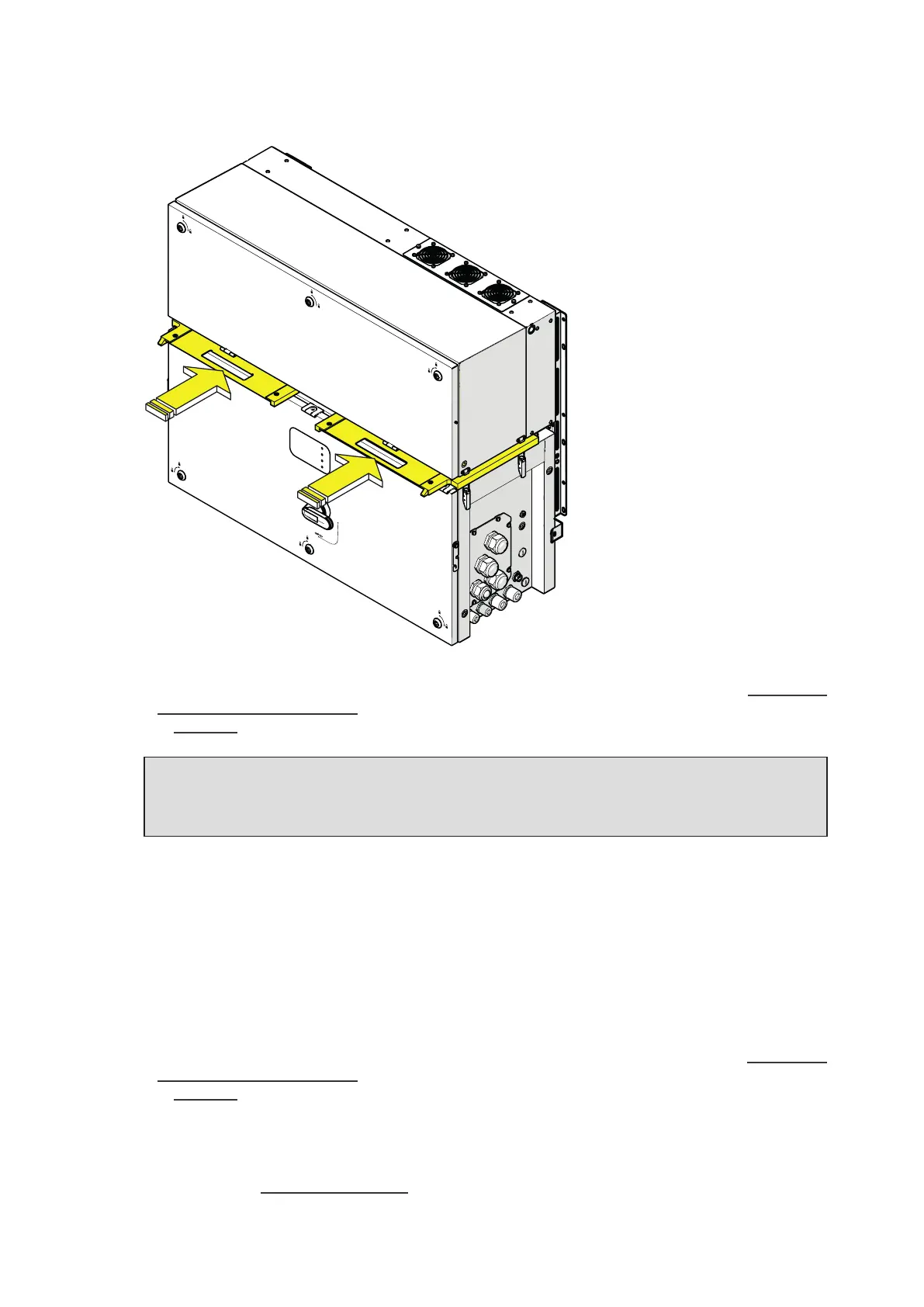
• Slide the gasket protective covers between power module (01) and wiring box (02) enclosures.
PVS
•
Remove the power module (01) following the indications for the mounting procedure in the “Assembly
the inverter to the bracket” paragraph in the reverse order and the indication for lifting methods
in “Lifting” paragraph.
ATTENTION – A Never leave the power module (01) or the wiring box (02) disassembled on
the field. In case is necessary to disassemble the power module (01) only, a IP65 protection
covers for wiring box openings (for temporary installation of wiring box only) kit is available
as accessory options.
To dismantling and disassemble the wiring box (02) follow these steps:
• Remove the power module (01) as previously described.
• Remove AC cables and protective earth clable.
• Remove any signal cables.
• Remove the wiring box (02) following the indications for the mounting procedure in the “Assembly
the inverter to the bracket” paragraph in the reverse order and the indication for lifting methods
in “Lifting” paragraph.
To dismantling and disassemble the mounting bracket (03) follow the indications for the mounting
procedure in the “Bracket assembly” paragraph in the reverse order.