4 Basics – flow measurement
4.1 Measurement principle PIOX S72*
2022-05-15, UMPIOX_S72xV1-9EN
14
4.1.2 Measurement of the flow velocity
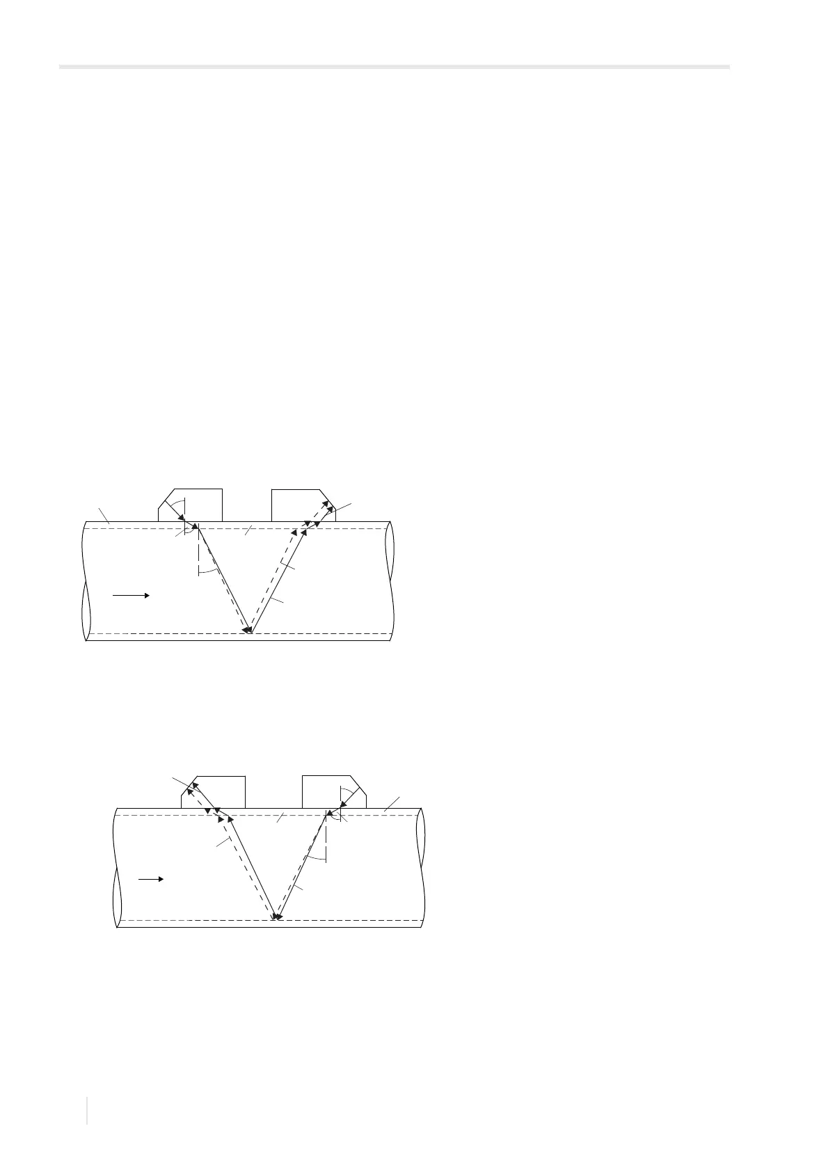
The signals are emitted and received by two transducers alternatively in and against the flow direction. If the fluid is
flowing, the signals propagating in the fluid are displaced with the flow.
Caused by this displacement, the sound path of the signal is reduced in flow direction and increased in the opposite
direction.
This causes a change in the transit times. The transit time of the signal in flow direction is shorter than the transit time
against the flow direction. The transit time difference is proportional to the average flow velocity.
The average flow velocity of the fluid is calculated as follows:
v=k
Re
·k
a
·
where
v – average flow velocity of the fluid
k
Re
– fluid mechanic calibration factor
k
a
– acoustic calibration factor
Δt – transit time difference
t
γ
– transit time in the fluid
Fig. 4.1: Sound path of the signal in the flow direction
c – sound speed
1 – transducer (emitter)
2 – transducer (receiver)
3 – pipe wall
Fig. 4.2: Sound path of the signal against the flow direction
c – sound speed
1 – transducer (emitter)
2 – transducer (receiver)
3 – pipe wall
c
β
β
α
γ
c
γ
3
21
c
α
c
α
reduction of the
sound path
flow direction of the fluid
sound path with flow
sound path without
flow
c
β
flow direction of the fluid
sound path with flow
sound path without
flow
β
α
γ
c
γ
increase of the sound
path
3
12
c
α
c
α