16 Outputs (TF7-*72***-******-******a-*****-**; a = M, P, Q)
16.1 Configuration of a digital output as binary output PIOX S72*
2022-05-15, UMPIOX_S72xV1-9EN
152
16 Outputs (TF7-*72***-******-******a-*****-**; a = M, P, Q)
If the transmitter is equipped with outputs, they have to be
configured. For the configuration of the analog output, see
section 10.3.6.
The transmitter can also be equipped with digital outputs. A
digital output combines the functions of the following
outputs:
• binary output (output of binary switching conditions)
• pulse output (integrating output of quantities)
• frequency output (scaled output of flow quantities)
These functions depend on the selected physical quantity.
16.1 Configuration of a digital output as binary output
A digital output switches if one of the following switching conditions is met:
– the measured value exceeds or falls below a limit
– the measured value lays within or outside a defined range
– a measurement is not possible
– an event occurs
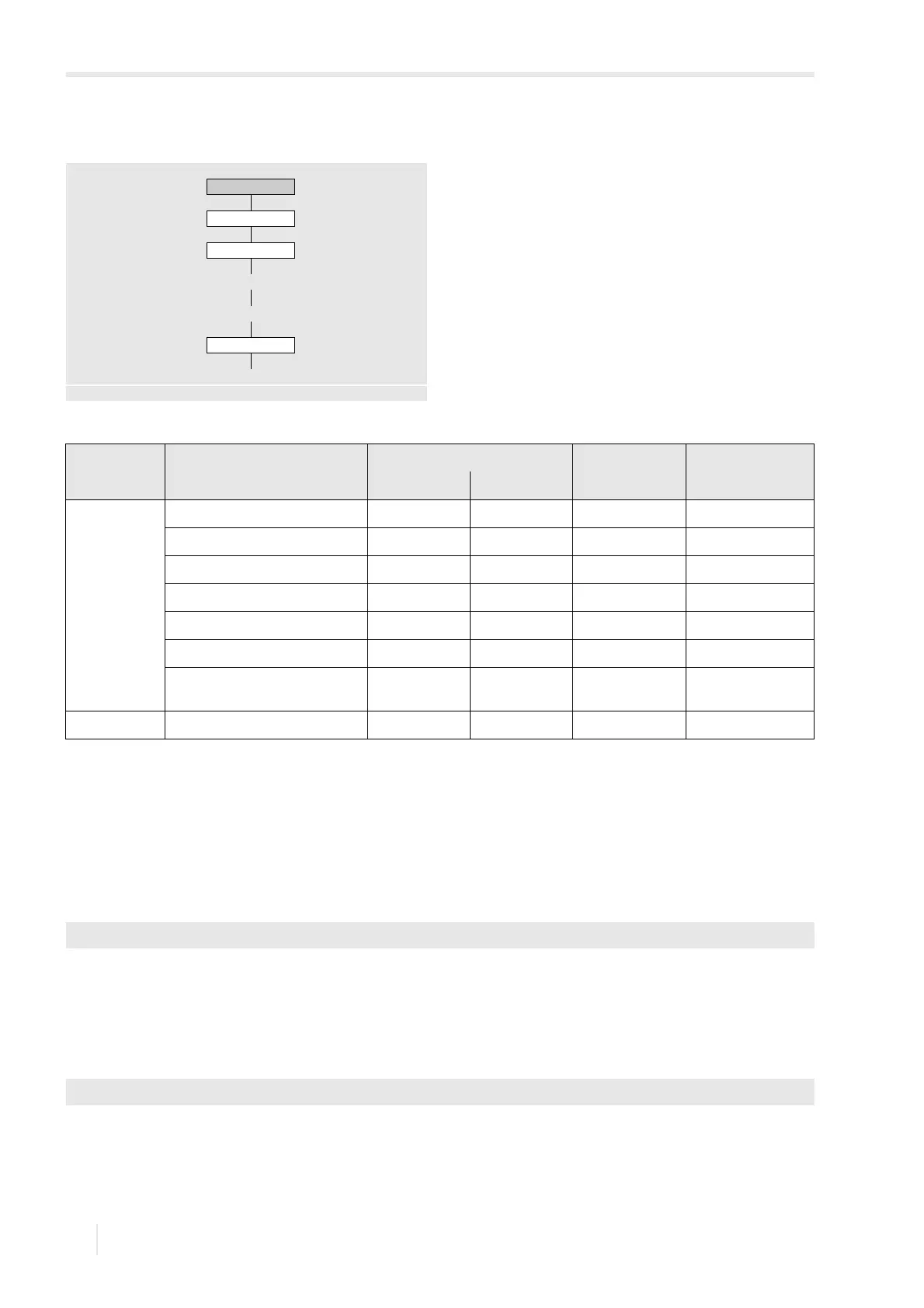
Assignment of an output
• Select the channel in the program branch Options (here: Channel A).
• Press ENTER.
This display will not be indicated if the transmitter has only one measuring channel.
• Select the list item Outputs.
• Press ENTER.
• Select an output to be assigned to the channel (here: Digital output B1).
• Press ENTER.
If the output has already been assigned to a channel, it is displayed as follows: Digital output B1 (A).
Options
Channel x
Outputs
Select output
Enable output
Source item
see annex A
Tab. 16.1: Output via digital outputs
source item binary output pulse output frequency output
status value event value
physical
quantities
Sound speed xx
Flow quantities xx
Totalizers xx
Pulse x
Fluid properties xx
Diagnostic values x
Miscellaneous
(Custom. Input 1...4)
xx
events Event trigger x
Options\Channel A
Options\Channel A\Outputs\Digital output B1(--)